Analysis of anatomic regions delineated from image data

an analysis and anatomic region technology, applied in the field of systems, can solve the problems of lack of robustness across a variety of real-world patients, complex set of tasks, lack of general purpose segmentation methods, etc., and achieve the effect of valuable morphologic information

Inactive Publication Date: 2009-10-29
STRATOVAN CORP
View PDF9 Cites 21 Cited by
  • Summary
  • Abstract
  • Description
  • Claims
  • Application Information

AI Technical Summary

Benefits of technology

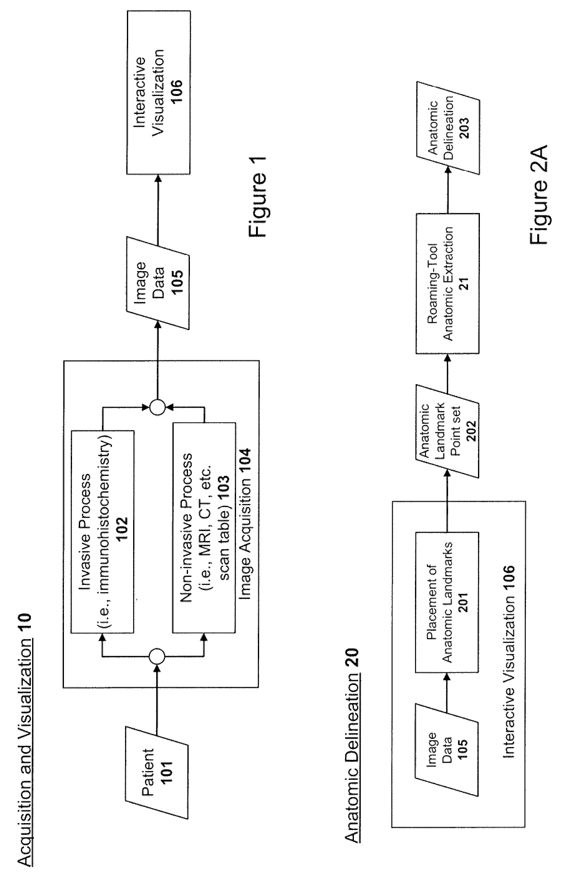
[0007]Certain embodiments of the present invention comprise systems and methods for delineating anatomy from medical image data. Source image data can be 2D images such as histology / immunohistochemistry images (color of grayscale) or 3D image data such as MRI, CT, PET, OCT, ultrasound, or from other image acquisition technologies that obtain a virtual representation of a patient. An anatomic region delineated from image data can provide valuable morphologic information. This shape information, usually in the form of landmark points or image pixel intensities, can provide the foundation for gathering statistical data establishing normal baselines. Furthermore, abnormal shape information can be compared to baselines to establish metrics for determining quantitative disease / injury severity, surgical indication, and possibly leading to computer aided diagnosis. Anatomic delineations can also be used to create patient-specific drill guides, surgical aids, and implants.

Problems solved by technology

Construction of a computer-based system replicating this knowledge and application thereof presents a complex set of tasks.
The main problem is obtaining an accurate anatomic representation to the extent that quantitative measurements can be taken reliably.
However, no general purpose segmentation method exists and most lack robustness across a variety of real-world patient data.
The most common problem is the accurate delineation of the anatomic boundary which can be obscured by (i) poor image representation, (ii) disease, (iii) varying image intensity values throughout the anatomic part, (iv) similarities with other anatomical parts, and (v) touching anatomical parts.
Furthermore, the boundary may simply be ill-defined such that general purpose image processing algorithms cannot accurately delineate anatomic boundaries.

Method used


Image

  • Analysis of anatomic regions delineated from image data
  • Analysis of anatomic regions delineated from image data
  • Analysis of anatomic regions delineated from image data

Examples


Embodiment Construction

[0023]Embodiments of the present invention will now be described in detail with reference to the drawings, which are provided as illustrative examples so as to enable those skilled in the art to practice the invention. Notably, the figures and examples below are not meant to limit the scope of the present invention to a single embodiment, but other embodiments are possible by way of interchange of some or all of the described or illustrated elements. Wherever convenient, the same reference numbers will be used throughout the drawings to refer to same or like parts. Where certain elements of these embodiments can be partially or fully implemented using known components, only those portions of such known components that are necessary for an understanding of the present invention will be described, and detailed descriptions of other portions of such known components will be omitted so as not to obscure the invention. In the present specification, an embodiment showing a singular compon...


PUM


Abstract

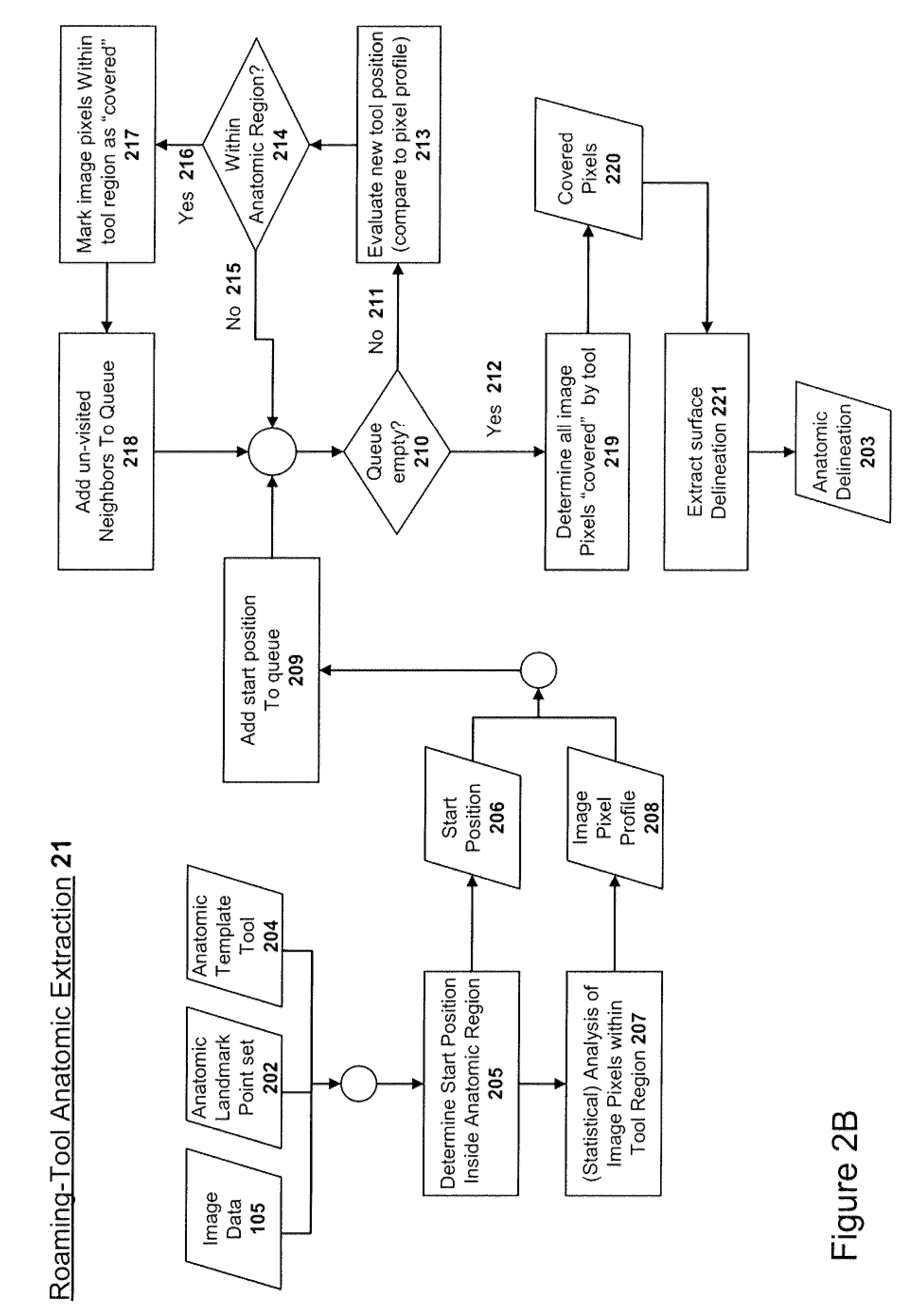
Systems and methods for delineating anatomical boundaries from two- and three-dimensional image data are described. A template shape is used to examine new image element (e.g. pixel and/or voxel) locations and determine boundary intersection based on characteristics determined from the plurality of image elements contained within this template. The result is a polyline/surface delineation of the desired anatomy, which can be used for morphometric/shape analysis, patient specific output, and knowledge-based queries.

Description

CROSS-REFERENCE TO RELATED APPLICATIONS[0001]The present application claims priority from U.S. Provisional Patent Application No. 61 / 047,982 filed Apr. 25, 2008, entitled “Orbit Morphology,” which is incorporated by reference herein in its entirety.BACKGROUND OF THE INVENTION[0002]1. Field of the Invention[0003]The present invention relates generally to imaging systems and more particularly to systems and methods for delineating anatomy from medical image data.[0004]2. Description of Related Art[0005]Medical treatment procedures based on medical image data often depend on morphological analyses of anatomic structures. Two-dimensional (2D) images from histology (immunohistochemistry) images and three-dimensional (3D) images from MRI, CT, PET, OCT, etc. imaging modalities provide computer accessible representations of a patient that can provide quantitative patient assessment. In the case of 3D MRI data, a radiologist examines the shape of a kidney, for example, as depicted in the ima...

Claims


Application Information

Patent Timeline
Patent Type & Authority Applications(United States)
IPC IPC(8): G06K9/00
CPCG06T7/0014G06T7/0085G06T17/00G06T2207/30084G06T2207/10088G06T2207/20136G06T2200/08G06T7/13G06T7/181
Inventor WILEY, DAVID
Owner STRATOVAN CORP
Why Eureka
Try Eureka