

Real-time biofilm monitoring system
- Summary
- Abstract
- Description
- Claims
- Application Information
AI Technical Summary
Benefits of technology
Problems solved by technology
Method used
Image

Examples
Embodiment Construction
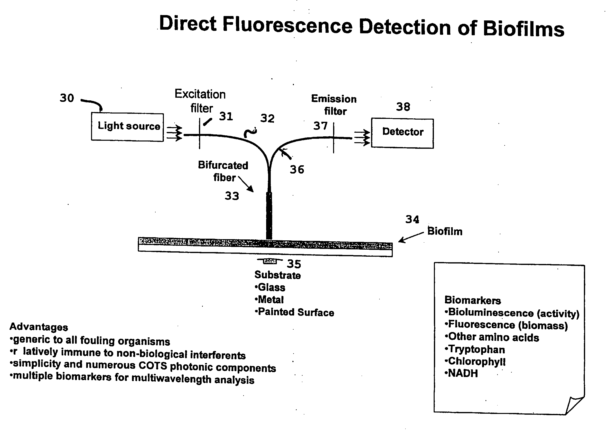
[0047] The system of the present invention is generic to all fouling organisms while being relatively immune to non-biological interferents. Its simplicity and numerous COTS photonic components provide multiple biomarkers for multiwavelength analysis.
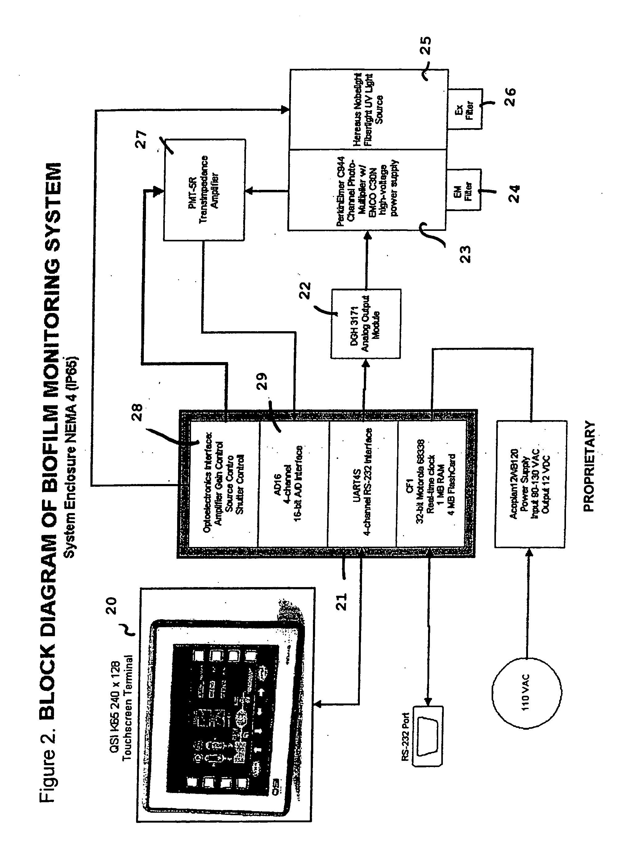
[0048]FIG. 2 is a block diagram of a biofilm monitoring system according to the present invention. The system is operated from a touch screen terminal 20 which is connected to a 4-channel RS-232 interface 21. This interface 21 is connected to an analog output module 22, connected to a C944 channel photomultiplier with a high-voltage power supply 23. The photomultiplier is provided with an emission filter. The photomultiplier is equipped with a fiber light UV light source 25, which has an excitation filter 26. The photomultiplier 23 is connected to a transimpedance amplifier 27 which is connected to both an optoelectronics interface amplifier 28 and a 4-channel 16-bit A / D interface 29.
[0049]FIG. 3 illustrates direct fluorescence detect...
PUM
 Abstract
Description
Claims
Application Information