Unlock instant, AI-driven research and patent intelligence for your innovation.

Porous membrane for fuel cell electrolyte membrane and method for manufacturing the same

a fuel cell electrolyte and porous membrane technology, applied in the direction of membranes, sustainable manufacturing/processing, cell components, etc., can solve the problems of large strength anisotropy generated in orthogonal two directions, inability to obtain sufficient strength by the perfluorosulfonic acid polymer itself, and difficulty in eliminating strength anisotropy, etc., to achieve high power generation performance, high strength, and high strength

Inactive Publication Date: 2009-10-29
TOYOTA JIDOSHA KK
View PDF12 Cites 11 Cited by
  • Summary
  • Abstract
  • Description
  • Claims
  • Application Information

AI Technical Summary

Benefits of technology

The present invention provides a porous membrane for a fuel cell electrolyte membrane that is strong and has high strength in two directions. The membrane is made by laminating two or more sheets of porous resin sheets with strength anisotropy in orthogonal two directions and bonding them together. The resulting membrane has equal mechanical properties in the longitudinal and lateral directions, which prevents stress strain difference between the two directions and ensures high power generation performance and long life of the membrane electrode assembly. The method for manufacturing the membrane is simple and effective.

Problems solved by technology

However, it is not possible to obtain sufficient strength by the perfluorosulfonic acid polymer itself.
This inevitably causes a large strength anisotropy to be generated in the orthogonal two directions.
However, the strength anisotropy is extremely difficult to be eliminated.
Further, in the case of biaxial stretching, it is difficult to form a membrane with a high stretching ratio (high orientation) as compared with the case of uniaxial stretching, so that a required strength as the porous membrane may be unable to be obtained.
In recent years, according to the requirement for the practical use of a fuel cell having higher power generation performance, it has become an important problem to impart a mechanical property which is equal in the longitudinal and lateral directions, to the porous membrane used as the reinforcing material.

Method used


Image

  • Porous membrane for fuel cell electrolyte membrane and method for manufacturing the same
  • Porous membrane for fuel cell electrolyte membrane and method for manufacturing the same
  • Porous membrane for fuel cell electrolyte membrane and method for manufacturing the same

Examples


embodiment

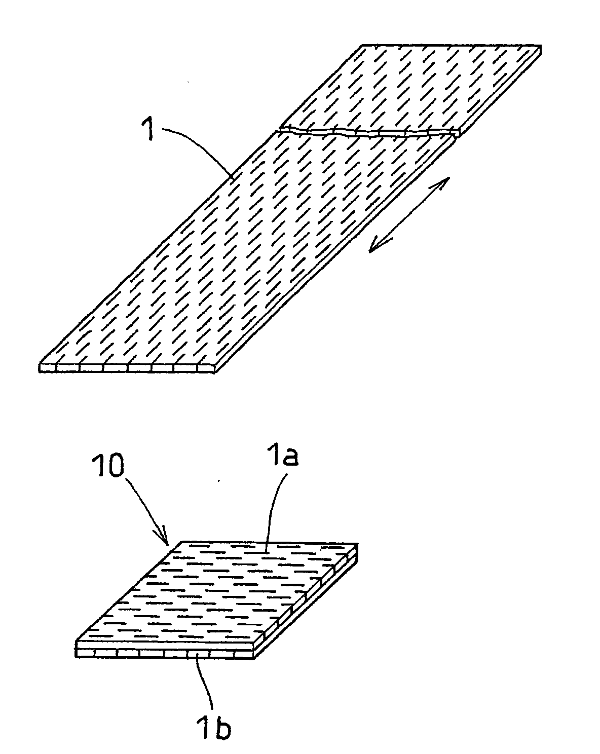
[0031]After a process of uniformly dispersing naphtha as a liquid lubricant in a fine powder of polytetrafluoroethylene (PTFE) and of preforming the obtained mixture, a round bar-like bead was obtained by subjecting the preformed mixture to paste extrusion. A long-sized unbaked tape was formed by making the bead be rolled between a pair of metallic rolling rolls. A fibril-like polytetrafluoroethylene resin porous sheet having a thickness of 7 μm was obtained by uniaxially and highly orienting (highly stretching) the tape (with stretching ratio of 10).

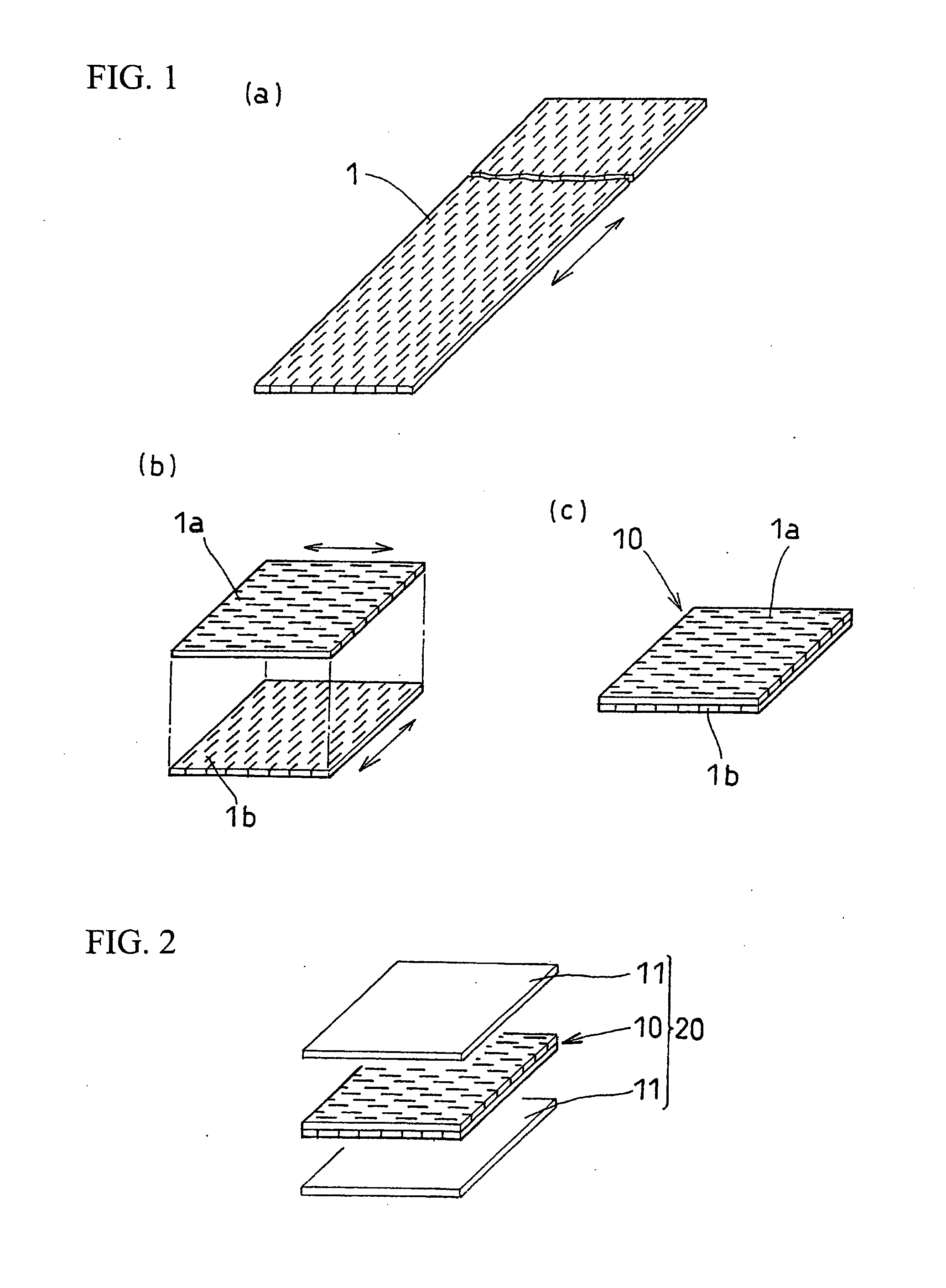
[0032]Two sheets having a size of 100 mm×100 mm were cut out from the obtained porous resin sheet, and were laminated so that the stretched directions are made to orthogonally cross each other. In laminating the sheets, the lamination interface between the sheets was coated by spraying a polytetrafluoroethylene suspension. The laminated sheets were heated at 360° C., so as to be integrally heat fused. As a result, a porous membrane for ...


PUM

PropertyMeasurementUnit
thicknessaaaaaaaaaa
sizeaaaaaaaaaa
thicknessaaaaaaaaaa

Abstract

To obtain a porous membrane for a fuel cell electrolyte membrane, having mechanical property which is equal in the longitudinal and lateral directions. A porous membrane 10 is formed in such a way that porous resin sheets 1a and 1b which are obtained by uniaxially stretching a polytetrafluoroethylene thin membrane and which have strength anisotropy in orthogonal two directions, are mutually laminated in a state where the directions in which the strength of the porous resin sheets is large are made to cross each other, and that the laminated porous resin sheets are integrally bonded by means of heat fusion, or the like.

Description

TECHNICAL FIELD[0001]The present invention relates to a porous membrane used as a reinforcing material in a fuel cell electrolyte membrane, and a method for manufacturing the porous membrane. Further, the present invention relates to an electrolyte membrane and a membrane electrode assembly which include the porous membrane.BACKGROUND ART[0002]A solid polymer fuel cell is known as one form of a fuel cell. The solid polymer fuel cell uses a membrane electrode assembly (MEA) 50 as a main component, as shown in FIG. 4. The membrane electrode assembly is held between separators 51 and 51 having fuel (hydrogen) gas passages and air gas passages, so as to thereby form a fuel cell 52 referred to as a unit cell. The membrane electrode assembly 50 has a structure in which an anode side electrode catalyst layer 56a and a diffusion layer 57a are laminated on one side of an electrolyte membrane 55 which is an ion exchange membrane, and in which a cathode side electrode catalyst layer 56b and a ...

Claims


Application Information

Patent Timeline
Patent Type & Authority Applications(United States)
IPC IPC(8): H01M8/10H01M4/82B32B7/035
CPCB01D69/12B01D2325/02B32B7/005B32B7/02B32B27/08Y10T29/49112B32B2457/18H01M8/106H01M8/1062Y02E60/521Y10T29/49114B32B2457/00B32B7/03Y02P70/50Y02E60/50B32B7/035B01D69/1213
Inventor HARADA, HIROSHI
Owner TOYOTA JIDOSHA KK