Eureka AIR delivers breakthrough ideas for toughest innovation challenges, trusted by R&D personnel around the world.

Spine surgery method and inserter

Inactive Publication Date: 2009-10-29
FABIAN HENRY F
View PDF69 Cites 84 Cited by
  • Summary
  • Abstract
  • Description
  • Claims
  • Application Information

AI Technical Summary

Benefits of technology

[0017]One advantage of this invention is that the inventive surgical inserter permits an implant to be relatively easily placed into a vertebral space.
[0018]Another advantage of this invention is that the implant may be relatively easily and securely attached to the inserter and then detached from the inserter.
[0019]Another advantage of this invention is that the surgeon may make consistent and reproducible biplanar, midline placement of the interbody implant.
[0021]Yet another advantage of this invention is that the surgical inserter allows for minimally invasive deployment via either an anterior, anterolateral, posterior or posterolateral approach, with the latter approach possible via either a transforaminal or extraforaminal approach.

Problems solved by technology

As a result, known spinal surgical methods, instrumentation and interbody implants have limitations.
One limitation is that the physical components are relatively large and bulky.
This reduces surgeon visualization of the surgical site.
Another limitation of known spinal surgical methods is that known surgical tools and implants are cumbersome and difficult to maneuver within the limited surgical space available.
The limitations of current instrumentation in MIS spine surgery are noted particularly with regards to interbody fusion surgery.

Method used


Image

  • Spine surgery method and inserter
  • Spine surgery method and inserter
  • Spine surgery method and inserter

Examples


first embodiment

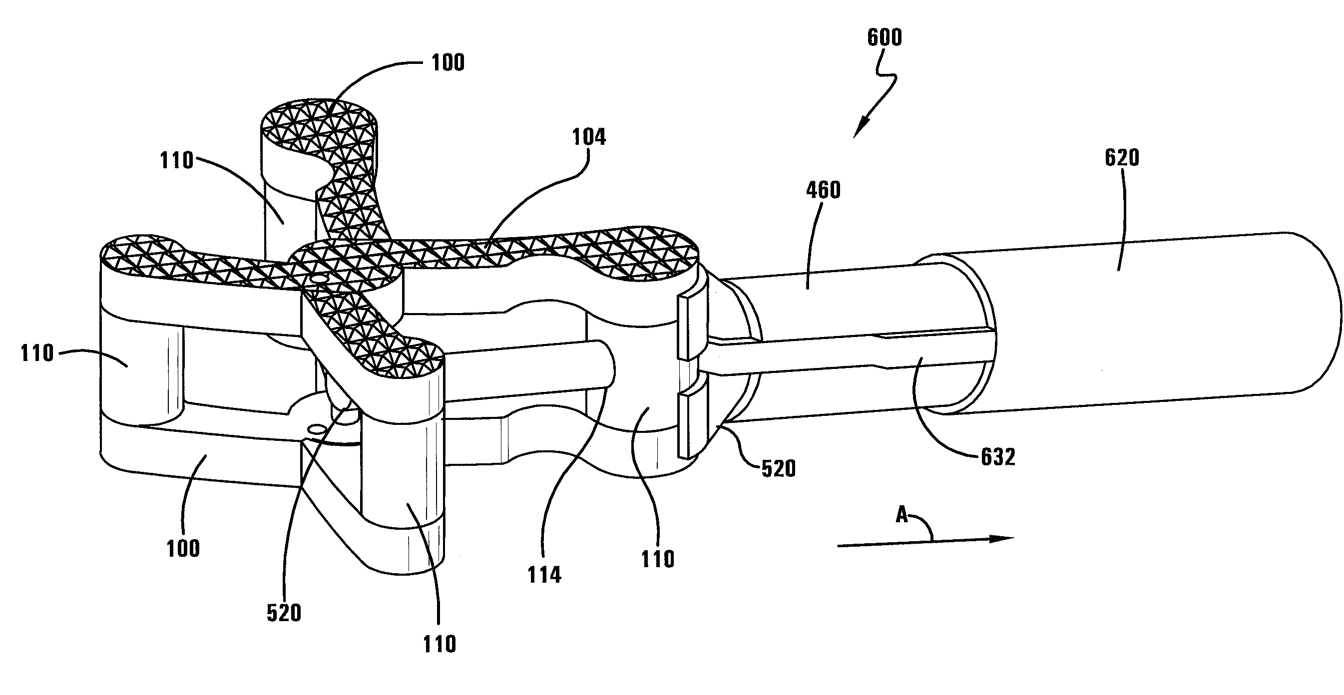
[0107]The first embodiment is shown in FIGS. 32-33. For this embodiment the wire 520 takes a linear path as it exits the inserter 200 and contacts the implant 100. In one specific embodiment, the post 110 gripped by the gripper 420 has a linear opening 114 that receives the wire 520 when it is extended out from the inserter 200. Continued extension of the wire 520 causes the distal end of the wire 520 to contact another implant surface, such as another post 110, to cause the implant 100 to deploy.

second embodiment

[0108]The second embodiment is shown in FIGS. 50-51. For this embodiment the wire 520 takes a curvilinear path as it contacts the implant 100. In one specific embodiment, the post 110 gripped by the gripper 420 has a curvilinear opening 116 that receives the wire 520 when it is extended out from the inserter 200. Continued extension of the wire 520 causes the distal end of the wire 520 to contact another implant surface, such as another post 110, to cause the implant 100 to deploy. In a more specific embodiment, the portion of the implant 100 that contacts the distal end of the wire 520 has a divot 118 on its surface that matches the surface shape of the distal end of the wire 520. In this way, the distal end of the wire 520 is received in the divot 118 making it easier for the wire 520 to stay in contact with the implant surface as it moves through the curvilinear motion.

[0109]With reference now to FIGS. 34-46, as also noted above with regard to a cable 560, in another embodiment a...


PUM


Abstract

A surgical inserter for use in inserting an implant into a vertebral space may include: (a) a handle; (b) a gripper having one end attached to the handle and a second end having a pair of arms; and (c) a grip activator having an opening that threadingly receives the gripper. The grip activator can be rotated in a first direction with respect to the gripper to cause the arms to move toward each other to grip the inserter and in a second direction with respect to the gripper to cause the arms to move away from each other to release the inserter. In one embodiment a compression force activator is used to deploy the implant and in another embodiment a tension force activator is used to deploy the implant.

Description

I. BACKGROUND OF THE INVENTION[0001]A. Field of Invention[0002]This invention pertains to the art of methods and apparatuses regarding spine surgery and more specifically relates to surgical procedures and an inserter used to position an implant, and perhaps to deploy the implant, within a vertebral space.[0003]B. Description of the Related Art[0004]The volume of spinal surgeries to treat degenerative disc and facet disease has steadily increased over the past decade, fueled by population demographics and advancements in diagnostic and instrumentation adjuncts. Improvements in intraoperative radiological imaging and surgical technique have generated a great deal of interest in applying minimally invasive surgical (MIS) techniques to spinal applications. As in other surgical subspecialties, it is hoped such minimally invasive techniques applied to spinal surgery will result in less soft tissue trauma, less operative blood loss, reduced operative time, faster recovery periods and lowe...

Claims


Application Information

Patent Timeline
IPC IPC(8): A61B17/58A61B17/00
CPCA61F2/442A61F2310/00179A61F2/4611A61F2002/30179A61F2002/30462A61F2002/30471A61F2002/30579A61F2002/4415A61F2002/4624A61F2002/4628A61F2002/4679A61F2220/0075A61F2220/0091A61F2230/0058A61F2310/00017A61F2310/00023A61F2310/00029A61F2310/00161A61F2/4455A61F2/46A61F2/4603A61F2/4425A61F2002/4622
Inventor FABIAN, HENRY F.
Owner FABIAN HENRY F
Why Eureka
Eureka Blog
Learn More