Architecture for maintaining constant voltage-controlled oscillator gain

a voltage control and oscillator technology, applied in the direction of automatic control, electrical equipment, etc., can solve the problems of reducing the noise sensitivity of the vco, vco will still have a nonlinear tuning characteristic, and the single port vco does not always enable adequate pll performance, etc., to achieve the effect of reducing the proportional path gain of the vco across the tuning range of the integral path

Inactive Publication Date: 2009-11-05
GLOBALFOUNDRIES INC
View PDF13 Cites 8 Cited by
  • Summary
  • Abstract
  • Description
  • Claims
  • Application Information

AI Technical Summary

Benefits of technology

[0011]To prevent the proportional path small-signal gain from changing as the VCO is tuned across its operating range by the integral path, the gain of the V-I converter on the proportional path is made to be a function of the voltage on the integral path. Selecting the appropriate function can result in a proportional path VCO gain that is constant across the integral path's tuning range.
[0012]In this invention, the proportional path V-I converter is decomposed into two V-I converters. The first V-I converter has fixed gain. The second V-I converter has variable gain proportional to 1-x where x is the output of the integral path V-I converter (normalized to having a range from 0 to 1). The outputs of the two proportional path V-I converters are connected together, meaning that their outputs are summed, and applied to the ICO. The gain of the composite proportional path V-I converter varies in a way that largely compensates for the non-linearity in the ICO's tuning characteristic. This allows for the variation in the VCO's proportional path gain across the integral path's tuning range to be reduced.

Problems solved by technology

Single port VCOs do not always enable adequate PLL performance due to tradeoffs associated with VCO gain.
This splitting reduces the VCO's noise sensitivity by allowing for substantial filtering on the high VCO gain path, however, the VCO will still have a nonlinear tuning characteristic.

Method used


Image

  • Architecture for maintaining constant voltage-controlled oscillator gain
  • Architecture for maintaining constant voltage-controlled oscillator gain
  • Architecture for maintaining constant voltage-controlled oscillator gain

Examples


Embodiment Construction

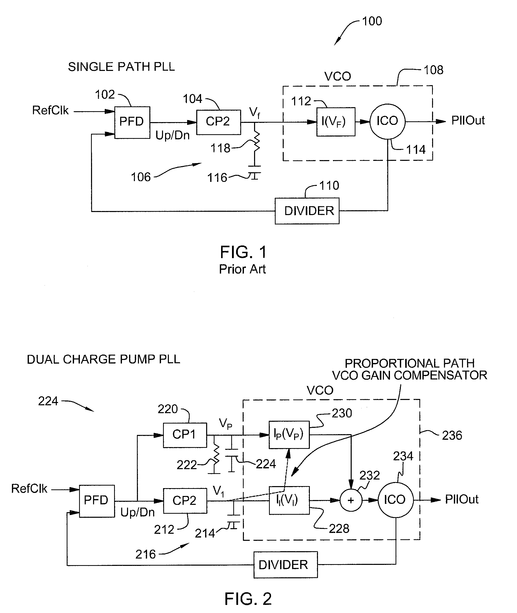
[0019]The preferred embodiment of the present invention relates to an architecture for maintaining constant the gain of a voltage-controlled oscillator, and the preferred architecture is very well suited for use in phase locked loops (PLLs). As an example, FIG. 1 illustrates a generic PLL relevant to the field of the invention.

[0020]Referring to FIG. 1 of the drawings, the reference numeral 100 generally designates a conventional PLL. A conventional PLL comprises a Phase-Frequency Detector (PFD) 102, a charge pump 104, a Low Pass Filter (LPF) 106, a VCO 108, and a frequency divider 110. The LPF 106 further comprises a capacitor 116 and a resistor 118. Also, the VCO 108 includes a voltage-to-current converter 112 and a current controlled oscillator 114.

[0021]The PLL 100 operates by maintaining charge on the first capacitor 116 of the LPF 106. A reference signal or input signal is input into the PFD 102 along with feedback from the frequency divider 110. Based on the comparison betwee...


PUM


Abstract

A voltage controlled oscillator and a method of operating a voltage-controlled oscillator are disclosed. The oscillator comprises a current controlled oscillator having a variable frequency current output, a first control path for generating a first control current having a first adjustable gain, and a second control path for generating a second control current having a second adjustable gain. A summer is provided for adding the first and second control currents to obtain a summed control current, and for applying the summed control current as an input current to the current controlled oscillator. A control sub-circuit is used for controlling the gain of the first control current as a function of a defined voltage on the second control path to maintain constant the gain of the current output of the current controlled oscillator over a given operating range of the current controlled oscillator.

Description

BACKGROUND OF THE INVENTION[0001]1. Field of the Invention[0002]The present invention generally relates to voltage-controlled oscillators, and more specifically, the invention relates to architectures for maintaining constant voltage controlled oscillator gain. Even more specifically, the preferred embodiment of the invention relates to such an architecture that is very well suited for use in phase-locked loops in order to make loop dynamics uniform across the tuning range of the voltage controlled oscillator.[0003]2. Background Art[0004]Phase-locked loops (PLLs) are commonly used to generate high-frequency signals in a wide variety of electronic circuit applications. Many important PLL parameters (jitter, settling time) depend on the bandwidth of the PLL. Loop bandwidth in turn depends on, among other parameters, the gain of the oscillator in the PLL. In the case of a voltage-controlled oscillator (VCO), the gain, which is the incremental slope of its output frequency vs. tuning vo...

Claims


Application Information

Patent Timeline
Patent Type & Authority Applications(United States)
IPC IPC(8): H03L5/00
CPCH03L7/0893H03L2207/06H03L7/0998H03L7/093
Inventor COWAN, GLENN E. R.FRIEDMAN, DANIEL J.MEGHELLI, MOUNIR
Owner GLOBALFOUNDRIES INC
Why Eureka
Try Eureka