Buffered optical fibre and method for improving the lifetime thereof

a technology of buffered optical fiber and lifetime, which is applied in the direction of cladded optical fiber, instruments, optics, etc., can solve the problems of premature failure, significant reduction of the operational life of the fibre, and damage at the bend of the fibre, so as to improve the lifetime of the fibr

Active Publication Date: 2009-11-05
PRYSMIAN SPA
View PDF9 Cites 19 Cited by
  • Summary
  • Abstract
  • Description
  • Claims
  • Application Information

AI Technical Summary

Benefits of technology

[0028]The present invention relates to a buffered optical fibre comprising a tight-buffer coating and a met

Problems solved by technology

Damage at fibre bends is driven by an increase in temperature when power lost at the bend is absorbed by the coating.
The heat energy can cause localized damage to the optical fibre and surrounding materials, which significantly reduces the operational life of the fibre.
Again, the escaping light energy is converted to heat upon leaving the cladding, which can overheat a localized portion of the optical transmission fibre, resulting in premature failure.
The Applicant observes that a drawback of this fibre is the need of carefully selecting refraction indexes of the coating layers sharply limits the choice of the first and second coating materials.
Furthermore, th

Method used


Image

  • Buffered optical fibre and method for improving the lifetime thereof
  • Buffered optical fibre and method for improving the lifetime thereof

Examples


example 1

Composition 1-4

[0102]Tight buffer coating materials according to the invention were made as set forth in Table 1.

TABLE 1Comp. 1Comp. 2Comp. 3*Comp. 4*Escorene ™ UL7085——LLPDE2015——Kisuma ™ 5-A160———Martinal ™ OL-107 / LE—180——Maleic anhydride20———grafted-EPR3-Aminopropyltri-—1.5——ethoxysilaneVestamide ™ 1670——100—Grilamid ™ L 20 LFEscorene ™ UL = Ethylene vinyl-acetate with 19% vinylacetate (by ExxonMobil);Kisuma ™ 5-A = synthetic magnesium hydroxide (by KYOWA Chemical Industry Co., LTD);Martinal ™ OL-107 / LE = aluminium hydroxide (by Albemarle);Vestamide ™ 1670 = polyamide 12;Grilamid ™ L 20 LF = graphite filled polyamide 12.

[0103]The amount of the material is provided in phr

[0104]Composition 3 and 4 are provided as comparison.

[0105]In the following Table 2 some properties of the compositions of Table 1 are set forth.

TABLE 2Comp. 1Comp. 2Comp. 3*Comp. 4*Density (Kg / dm3)1.481.531.011.08Thermal diffusivity [m2 / 0.2360.2170.1060.142(sec · 10−6)]Thermal conductivity0.6810.6240.2900.350(W / m...

example 2

Analysis of Buffered Optical Fibre Failures

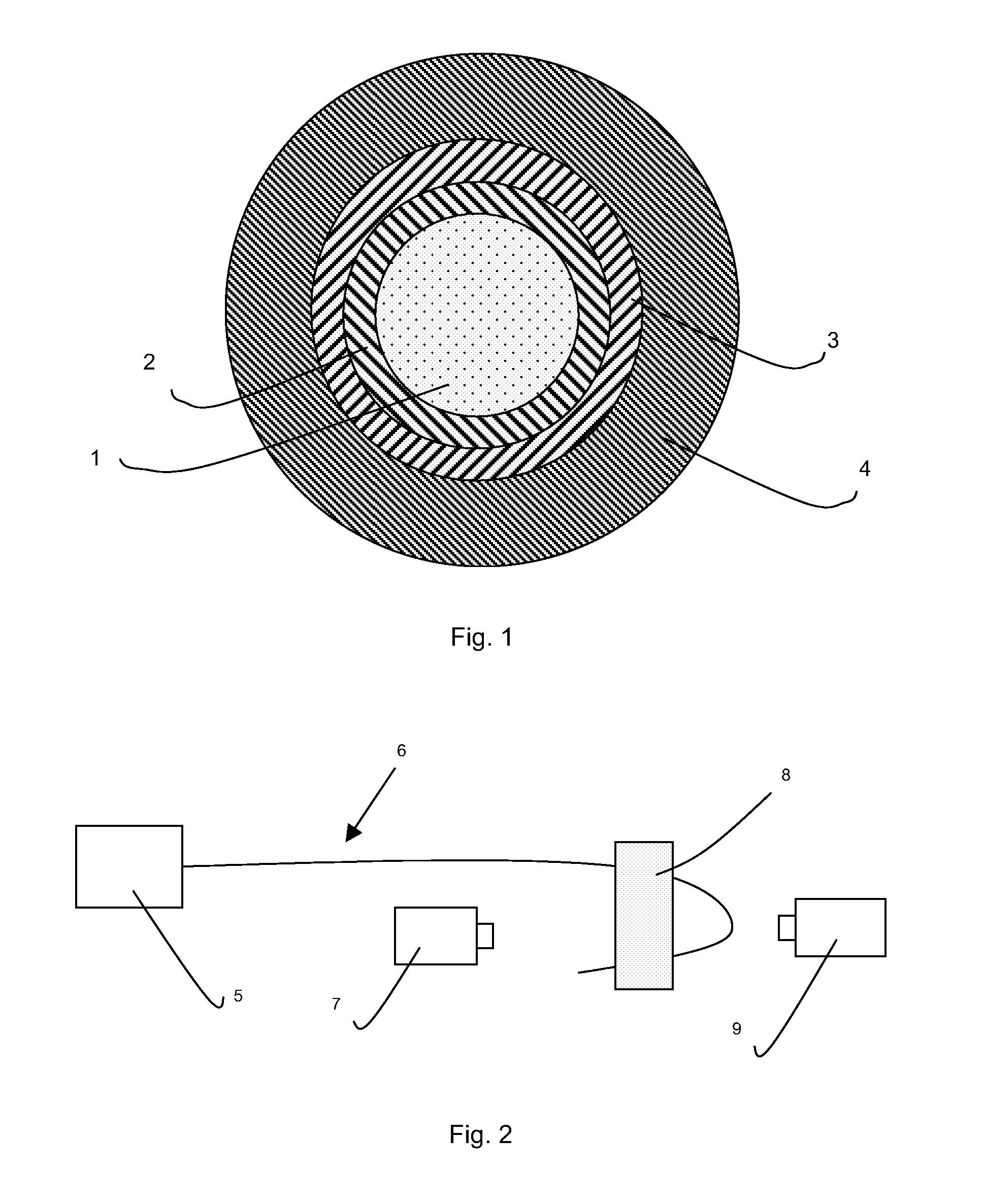
[0106]Buffered optical fibres were tested by the set-up described by I. M. Davies et al. supra, and sketched in FIG. 2. The buffered optical fiber (6) to be tested was connected to a laser (5) with an output power of 1 W and positioned with a minimum bend radius of 4 mm by a bending device (8). The heating of the curved portion of the buffered optical fiber was measured by a thermo camera (9) while the appearance of buffered the optical fibre during the test was recorded by an imaging camera (7). The maximum temperature reached by the fibres and the behavior thereof were measured.

[0107]Two commercial optical fibres SM Light (by Prysmian Cavi e Sistemi Telecom) with DeSolite® 3471-1-129 as first exterior coating and DeSolite® 3471-2-136 as second exterior coating were tested according to the set-up discussed above. The first one (F1) was provided with a loose buffer coating made with the composition 1 of Example 1, while the second one (F2) ...


PUM

PropertyMeasurementUnit
Percent by massaaaaaaaaaa
Thicknessaaaaaaaaaa

Abstract

A buffered optical fibre includes an optical waveguide, at least one exterior coating surrounding the optical waveguide and a buffer coating surrounding the at least one exterior coating, wherein the buffer coating is a tight buffer coating made of a material having a density of at least about 1.2 Kg/dm3, a thermal conductivity of at least about 0.4 W/m·K and includes a polymeric matrix and an inorganic filler.

Description

BACKGROUND OF THE INVENTION[0001]1. Field of the Invention[0002]The present invention relates to a buffered optical fibre and a method for improving the lifetime thereof.[0003]More particularly, the present invention relates to a buffered optical fibre comprising a tight-buffer coating and a method for improving the lifetime thereof under high power and small diameter bend improving the energy removal therefrom.[0004]2. Description of Related Art[0005]An optical fibre generally comprises a core surrounded by a cladding (hereinafter both collectively referred to as “optical waveguide”), said core and cladding being preferably made of glass, and at least one exterior coating.[0006]In many instances, the exterior coatings are two. The exterior coating directly contacting the optical waveguide is called “first coating” or “primary coating” and the exterior coating overlying the first one is called “second coating” or “secondary coating”. Typically, said first and second coatings are mad...

Claims


Application Information

Patent Timeline
IPC IPC(8): G02B6/44C03C25/106C03C25/47
CPCC03C25/101G02B6/02395G02B6/4402C03C25/106C03C25/47
Inventor DEBUT, ALEXISSARCHI, DAVIDECONSONNI, ENRICOTRAVAGNIN, MARTINO
Owner PRYSMIAN SPA
Why Eureka
Try Eureka