Force limiting tensioning arm

Inactive Publication Date: 2009-11-05
BORG WARNER INC
View PDF12 Cites 6 Cited by
  • Summary
  • Abstract
  • Description
  • Claims
  • Application Information

AI Technical Summary

Benefits of technology

[0019]This invention provides a tensioner which maintains a tension force on the chain that is substantially constant throughout the wide spectrum of tension conditions exhibited by the chain during engine operation, engine shut down and “engine off” modes. The biasing force of the resilient pad and the pre-load of the sup

Problems solved by technology

Prevention of such slippage is particularly important in the case of a chain driven camshaft in an internal combustion engine because the jumping of teeth will throw off the camshaft timing, causing damage to the power transmission system or possibly rendering the engine inoperative.
However, in the harsh environment of an internal combustion engine, various factors can cause fluctuations in chain tension.
For instance, wide variations in temperature and thermal expansion coefficients among the various parts of the engine can cause chain tension to vary between excessively high or low levels.
During prolonged use, wear to the components of the power transmission system can cause a decrease in chain te

Method used


Image

  • Force limiting tensioning arm
  • Force limiting tensioning arm
  • Force limiting tensioning arm

Examples


Example

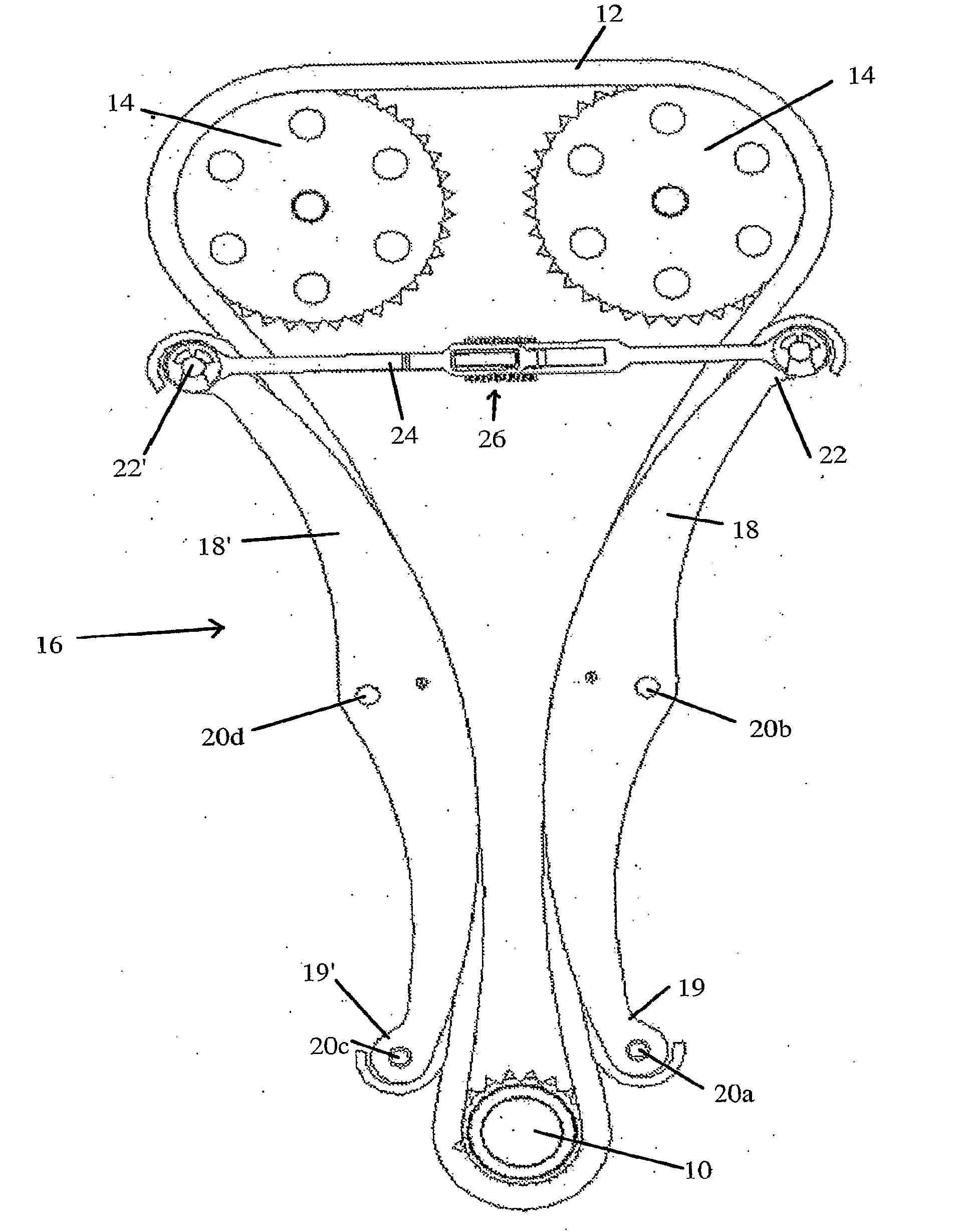
[0031]A tensioner assembly representative of one that might be used with the force limiting tensioner of the present invention is shown in FIG. 5 in combination with a typical power transmission drive system for an internal combustion engine. A drive sprocket transmits energy from the engine's crank shaft (not shown) via a belt or chain 12 to at least one driven sprocket 14. A chain drive is most common. The driven sprocket(s) 14 typically drive the at least one cam shaft of the internal combustion engine which, in turn, control cylinder valve timing. The strands of chain that mm from either the drive sprocket to the at least one driven sprocket or visa versa vary in tension in response to different engine conditions. During engine operation, one strand is substantially tighter than the other strand, which is considered slack by contrast. In systems where the chain engages toothed sprockets, a tensioning device 16 must be employed to prevent tooth skipping over a wide range of chain...


PUM


Abstract

A tensioner for a chain driven power transmission system of an internal combustion engine, having a ratchet as part of the tensioning system is disclosed. The tensioner contains at least one bracket that is pivotally mounted to the engine adjacent one strand of the chain. The bracket contains a chain guide element that maintains forceful slideable engagement with the chain. Between the chain guide element and the bracket are an elongated support member having a pre-loaded spring force and an elongated resilient pad. The resilient pad quickly compresses in response to spikes or surges in chain tension absorbing the force of the spike.

Description

REFERENCE TO RELATED APPLICATIONS[0001]This application is a continuation in part of application Ser. No. 11 / 168,049, filed on Jun. 28, 2005, entitled “Pivoting Mechanical Tensioner With A Compliant Blade Spring”. The aforementioned application is hereby incorporated by reference.BACKGROUND OF THE INVENTION[0002]1. Field of the Invention[0003]The invention pertains to the field of tensioners used in chain drive power transmission systems. More particularly, the invention pertains to the use of a resilient pad in combination with an optional pre-loaded spring under a chain sliding face to carefully regulate spikes or excessive surges in chain tension.[0004]2. Description of Related Art[0005]A tensioning device, such as a hydraulic tensioner, is used as a control device for a power transmission chain, or similar power transmission devices, as the chain travels between a plurality of sprockets. In this device, the chain transmits power from a driving shaft to a driven shaft, so that at...

Claims


Application Information

Patent Timeline
IPC IPC(8): F16H7/08
CPCF16H7/0848F16H2007/0874F16H2007/0853F16H2007/0804
Inventor MARKLEY, GEORGE L.
Owner BORG WARNER INC
Why Eureka
Try Eureka