Method and apparatus for configuring a device

a technology of electronic devices and configuration methods, applied in the field of configuration methods and apparatuses, can solve the problems of difficult to tell exactly which blocks need to be powered up, difficult to appreciate which registers, and modified, etc., and achieve the effect of improving the efficiency of configuring an electronic device, faster time-to-market for development, and faster control of the devi

Inactive Publication Date: 2009-11-05
WOLFSON MICROELECTRONICS LTD
View PDF8 Cites 12 Cited by
  • Summary
  • Abstract
  • Description
  • Claims
  • Application Information

AI Technical Summary

Benefits of technology

[0070]Embodiments of the present invention can provide a significant improvement in the efficiency of configuring an electronic device being evaluated or configured. This allows the engineer to concentrate on their core task of evaluating the device and optimising or debugging their use of it. It also allows them to develop software to control the device faster, allowing faster time-to-market for development of an end-user product.

Problems solved by technology

This means that customers have to work out exactly which components they need to modify to achieve the desired effect.
Moreover, it is not easy to appreciate which registers need to be modified (or how) to set up the desired path.
Another problem is that it is difficult to tell exactly which blocks need to be powered up to set up the required path.
It is easy to miss a required block, in which case the path will not work.
Conversely, it is easy to leave unnecessary blocks powered up, using more power than required.
When evaluating or configuring audio devices with complex filters it can be difficult to visualise the effects of the filters and how they interact.
Configuring these settings is frequently a matter of trial and error—making changes and listening to the result with test signals until the desired effect has been achieved.
On the other hand it is still difficult to get an overview of what is involved for the whole desired path or effect.
For example, with reference to the FIG. 3E control panel for tone and ALC control, it is difficult to get a feel for exactly how this will affect the output waveform.
As another example, referring to the audio path shown in FIG. 1B, unless the engineer is intimately familiar with the device, setting up this path will still require her to cross-reference the datasheet frequently, and there remains the above-mentioned problem of knowing which blocks to power up.
However, it is still difficult to get a feel for exactly how the settings will affect the operation of the device, for example the output waveform in the case of a filter.
A lot of trial and error is required to achieve the desired effect.
The test file cannot be played back in real time—there is a laborious conversion step.
To summarise, the prior art gives control of individual components, but none of it allows the engineer to configure the device as a whole.
This requires the engineer to spend a lot of time thinking about which blocks are involved and spend a lot of time ensuring they get the best out of the device.
Likewise, the prior art gives control of the filter components, but a lot of trial and error is required to configure the device to achieve the required effect.

Method used


Image

  • Method and apparatus for configuring a device
  • Method and apparatus for configuring a device
  • Method and apparatus for configuring a device

Examples


first embodiment

Interactive Audio Routing Diagram

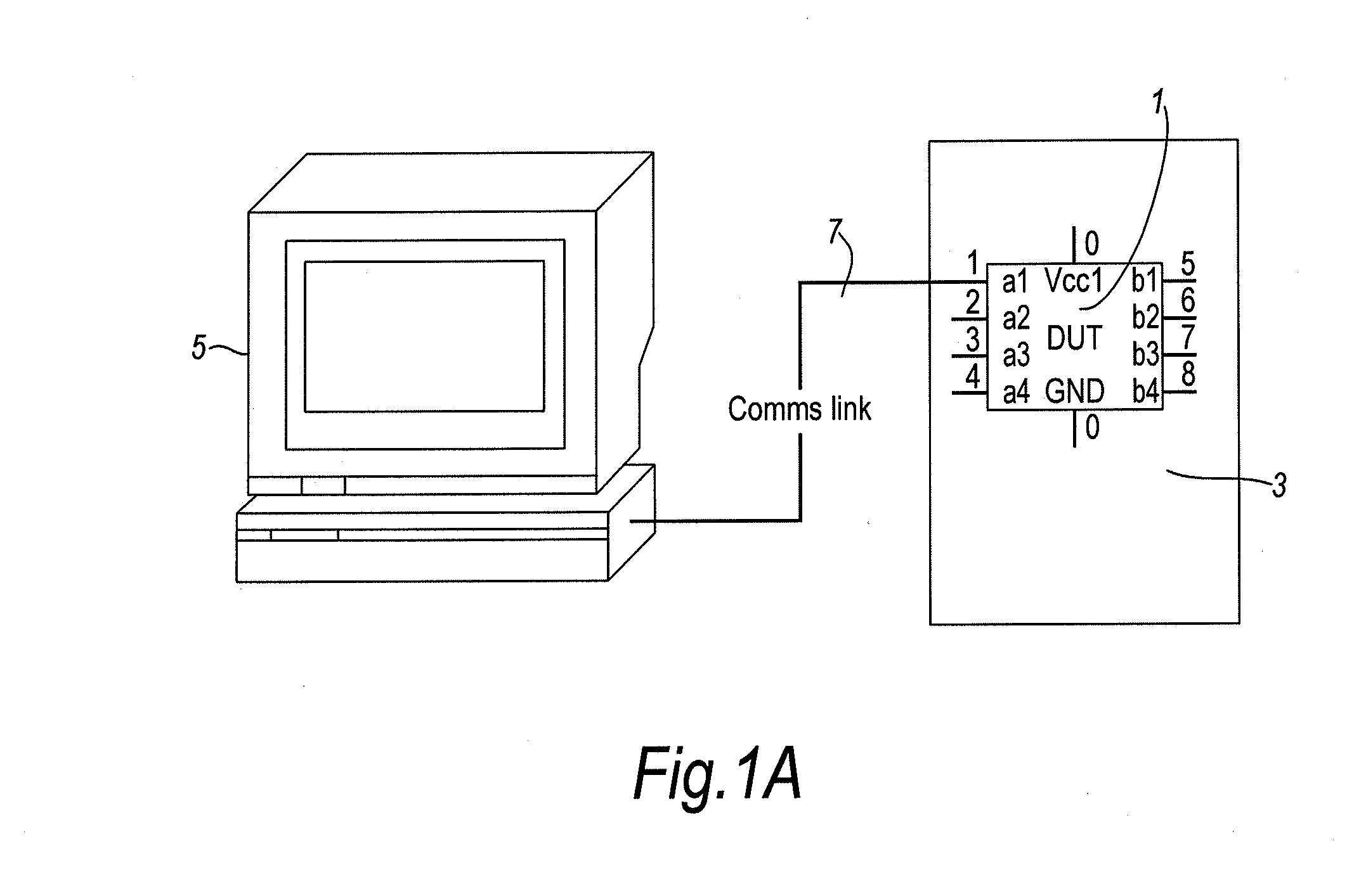
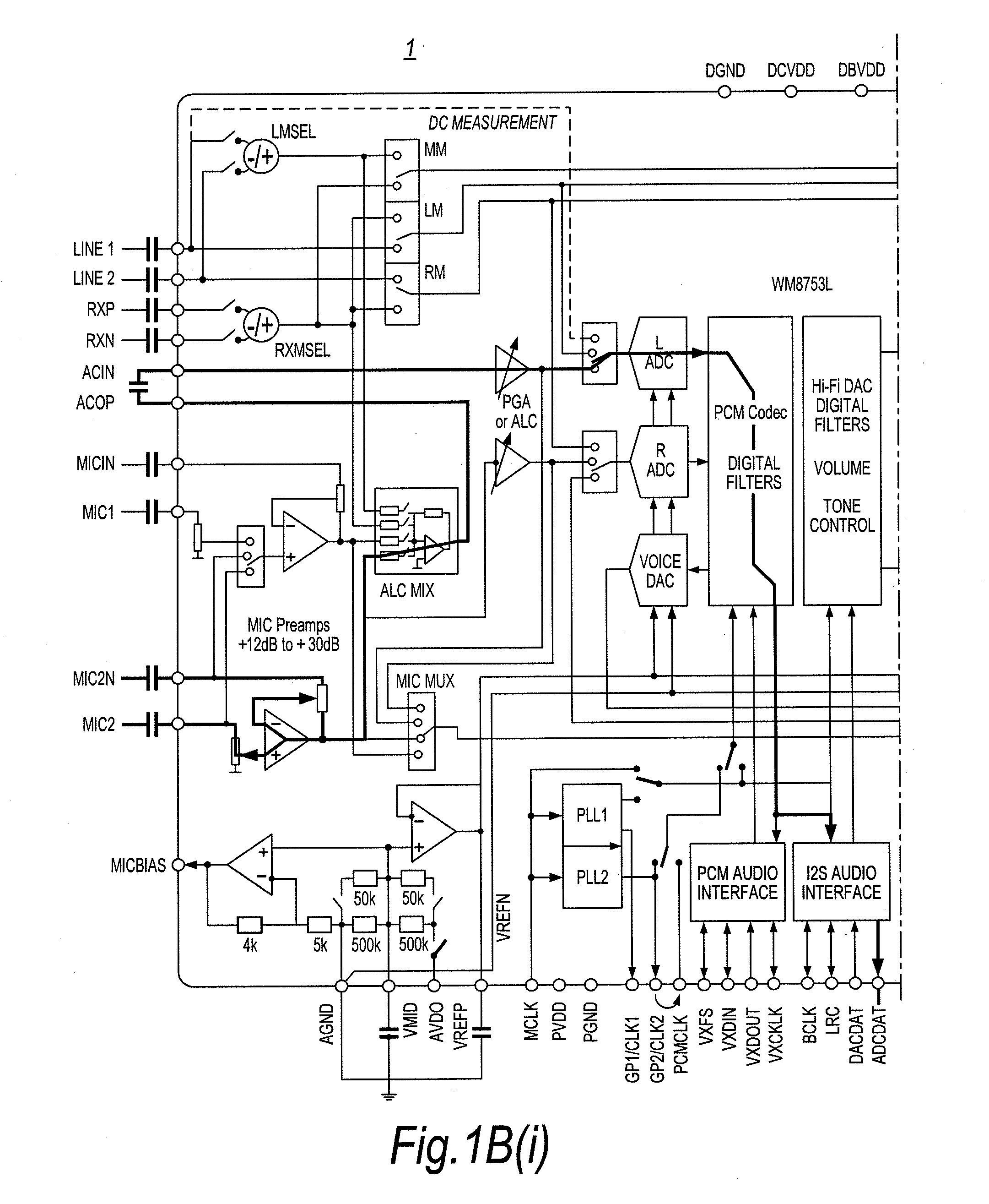
[0086]A first embodiment is an interactive audio routing diagram which may take the form, for example, as shown in FIG. 6. This presents, on a screen such as the monitor of computer 5 in FIG. 1A, a block diagram 50 of the main components of the device, in this case the same audio IC as depicted in FIG. 1B. Indeed, the resemblance between FIG. 1B and FIG. 6 will be noted. The difference now is that the diagram 50 is interactive, allowing a user (typically, an engineer) to select components and connections between them in order to set up a particular routing. Typically, this will be achieved by the user operating an input device such as a mouse, operated in known ways for interacting with a graphical user interface of a personal computer. For example, in a windowing-type environment, tabs can be used to switch between different windows. As will be seen in the Figure, the interactive block diagram 50 is selected by means of a tab 50a. The screen display...

second embodiment

Interactive Clocking / PLL / FLL Diagram

[0115]As already mentioned, there are various aspects to the operation of a complex electronic device. In the case of an audio IC, for example, audio routing as illustrated in FIG. 6 is only one aspect. Another configuration aspect is the clocks applied to various parts of the IC. FIG. 7 illustrates a second embodiment of the present invention in which an interactive block diagram 60 is provided to handle configuration of clocks (such as master clock MCLK 61), phase-locked loops (PLLS, such as PLL162) and / or frequency-locked loops (FLLs) of an electronic device. The interactive block diagram 60 is selected, for example, by clicking on a tab 60a for Clocking, located along the upper edge of the screen display. Thus, a user can proceed directly from another interactive block diagram, such as interactive block diagram 50 for audio routing as already discussed, to the present diagram 60 to configure the clocks, PLLs and FLLs.

[0116]This interactive blo...

third embodiment

Interactive GPIO Diagram

[0124]Some devices have multi-function or general-purpose inputs and outputs (the term “GPIO” will be considered to cover both), with quite complex control hierarchies. Continuing with the example audio IC used previously, FIG. 8 shows an interactive block diagram 70 for general purpose I / O configuration as another embodiment of the present invention. The user can select this diagram for display by clicking on a tab 70a. The example shown allows configuration of a single GPIO pin of the device; in this instance GPIO 5 has been selected (as indicated by 71).

[0125]This embodiment applies the same principles of direct interaction and manipulation to the GPIO diagram. Thus, switch settings (such as FUNCTION SELECT 72 in FIG. 8) are altered by clicking directly on the block diagram, and the currently active paths are highlighted and enabled paths are instantly visible.

[0126]Corresponding features and effects are provided as for the first embodiment and the second ...


PUM


Abstract

To facilitate evaluation, testing and / or configuration of an electronic device, one or more interactive setting diagrams are provided in the form of a block diagram for showing inter-relationships of functional blocks of the device, and / or a diagram for showing signal processing functions of the device. In the case of an audio IC for example, respective block diagrams may be provided for audio routing, for clocking, for general purpose I / IO, and so on. Likewise, signal processing may be represented by diagrams for configuring filters and ALC. The diagrams are displayed on a display of a computer, having an input device which the user operates to change settings of the device. The user can interact directly with the interactive setting diagram by manipulating graphical controls incorporated into the diagram. Thus, for example, an audio path can be set by clicking on a signal line shown in the diagram, or filter settings modified by moving sliders displayed alongside a filter characteristic graph. Settings made in this way can be recorded for future re-use and / or reflected immediately in a register map of the device which may be connected to the computer via an evaluation board and interface.

Description

TECHNICAL FIELD[0001]The present invention relates to a configuration method and apparatus, and in particular to an method and apparatus for configuring an electronic device. Here, “configuring” also refers to evaluating, testing or controlling the electronic device.BACKGROUND[0002]Manufacturers of electronic devices often provide evaluation tools for use by their engineers and their customers. These tools enable engineers to set or change various settings of the electronic device, for example for testing or evaluation purposes during a system design. In this situation, the device is referred to as a Device Under Test (DUT). In addition to the ability to change various settings on the DUT, engineers may also need to retrieve and monitor the current settings.[0003]There are a number of different scenarios where evaluation tools are used. FIG. 1A shows an example of a first scenario in which a DUT 1 is placed on an evaluation board 3 and controlled using a separate computer 5. The eva...

Claims


Application Information

Patent Timeline
Patent Type & Authority Applications(United States)
IPC IPC(8): G06F3/048G06F15/177
CPCG06F11/2247G06F3/165
Inventor BROCKBANK, IAN BOWMAN
Owner WOLFSON MICROELECTRONICS LTD
Why Eureka
Try Eureka