Method of Determining An Optical Distance For Chromatic Dispersion Compensation

Active Publication Date: 2009-11-12
II VI DELAWARE INC
View PDF8 Cites 12 Cited by
  • Summary
  • Abstract
  • Description
  • Claims
  • Application Information

AI Technical Summary

Benefits of technology

[0013]One advantage of the disclosed method is that it allows tunable dispersion compensation of a wavelength channel to be periodically optimized at each node

Problems solved by technology

When a light wave travels through a medium, such as an optical fiber, each wavelength contained in the light wave travels at a different speed, resulting in chromatic dispersion.
Chromatic dispersion leads to signal degradation since the varying delay in arrival time between the different constituent components of a WDM signal causes the different wavelength channels of a WDM signal to arrive at a given destination node at different times. Thus, a misalignment in time is produced between the different wavelength channels of a WDM signal when transmitted from node to node within a system.
Pulse spreading, if uncorrected, typically causes interference between adjacent light pulses, resulting in increased bit rate error.
One drawback to using fixed dispersion compensation is that it is unable to adequately correct for chromatic dispersion in evolving optical networks.
Because the chromatic dispersion is oftentimes a function of variable environmental conditions, an initial representative measurement of dispersion produced within the optical link may not be able to provide an accurate estimate of chromatic dispersion, especially with the accuracy required by high-speed optical systems.
In add

Method used


Image

  • Method of Determining An Optical Distance For Chromatic Dispersion Compensation
  • Method of Determining An Optical Distance For Chromatic Dispersion Compensation
  • Method of Determining An Optical Distance For Chromatic Dispersion Compensation

Examples


Embodiment Construction

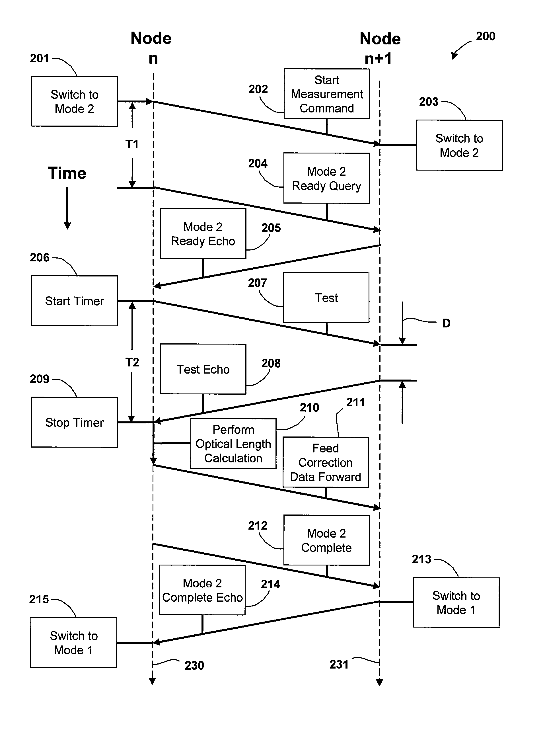
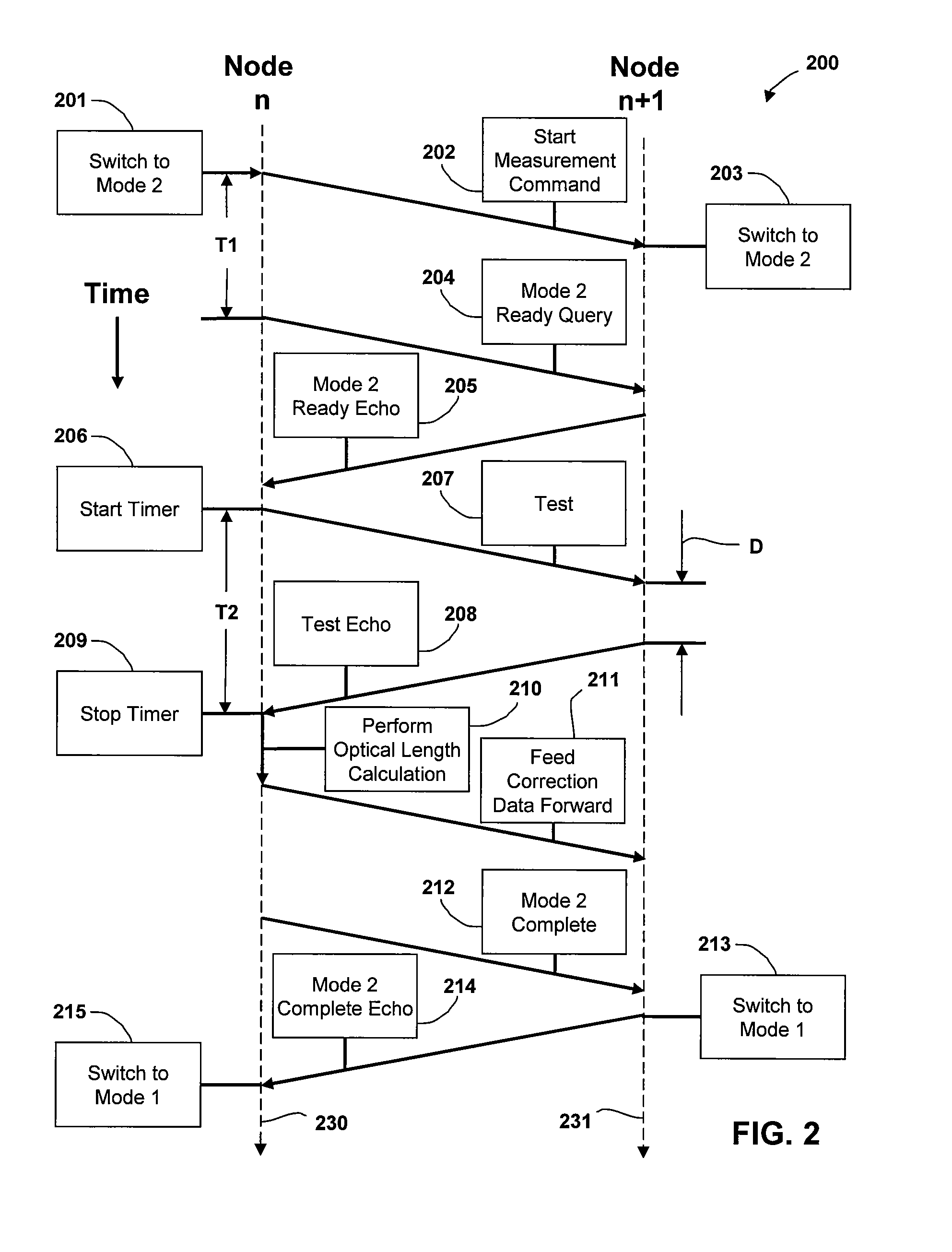
[0018]Embodiments of the invention contemplate a method of determining optical distance in an optical link using existing optical supervisor channel (OSC) transceivers and associated hardware. An OSC signal transmitted between adjacent nodes of an optical network determines the “time of flight” of an optical signal having a known wavelength, thereby allowing direct calculation of the optical distance between the two nodes. In this way, tunable dispersion compensation of a wavelength channel can be periodically optimized at each node in response to incremental changes in environmental factors that affect chromatic dispersion produced between the two nodes or in response to network reconfigurations that affect the chromatic dispersion produced between the two nodes.

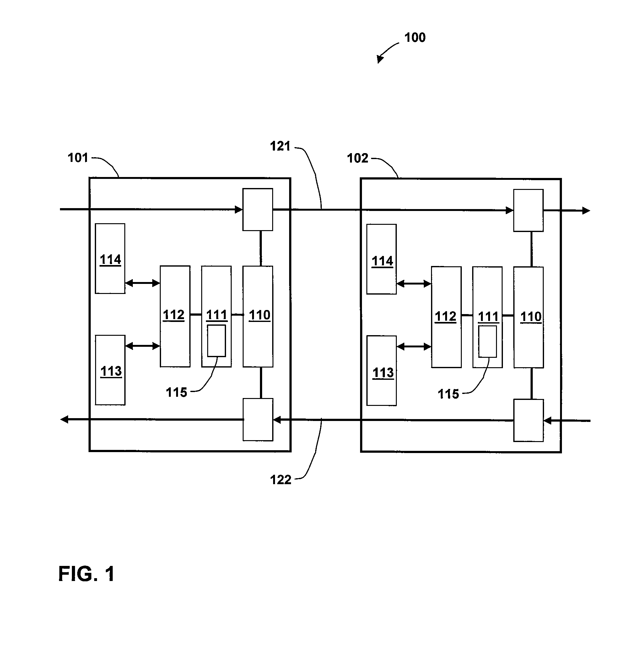
[0019]FIG. 1 illustrates a portion of an optical network 100 that includes two nodes. Nodes 101, 102 are adjacent nodes in optical network 100, e.g., nodes n, n+1, respectively. In addition to other components related to th...


PUM


Abstract

A method of determining an optical distance between two nodes of an optical network for chromatic dispersion compensation includes using existing optical supervisory channel components in each node to measure the “time-of-flight” of an optical signal having a known wavelength. The effective optical distance is determined based on the time-of-flight and known wavelength of the optical signal. The computed optical distance may then be used to compensate for the dispersion experienced by the optical signal when transmitted between the two nodes. Advantageously, the method allows tunable dispersion compensation of a wavelength channel to be periodically optimized at each node in response to incremental changes in environmental factors that affect the chromatic dispersion produced between the two nodes or in response to reconfigurations that affect the chromatic dispersion produced between the two nodes.

Description

BACKGROUND OF THE INVENTION[0001]1. Field of the Invention[0002]Embodiments of the present invention relate generally to optical communication systems and, more particularly, to a method of determining optical distance for chromatic dispersion compensation.[0003]2. Description of the Related Art[0004]In a wavelength division multiplexing (WDM) optical communication system, information is carried by multiple channels, each channel having a unique wavelength. WDM allows transmission of data from different sources over the same fiber optic link simultaneously, since each data source is assigned a dedicated wavelength channel. The result is an optical communication link with an aggregate bandwidth that increases with the number of wavelengths, or channels, incorporated into the WDM signal. In this way, WDM technology maximizes the use of an available fiber optic infrastructure-what would normally require multiple optical links instead requires only one. As defined herein, an “optical li...

Claims


Application Information

Patent Timeline
IPC IPC(8): H04B10/20
CPCH04B10/2513H04B10/0775
Inventor DUAN, XIAODONGBARBAROSSA, GIOVANNI
Owner II VI DELAWARE INC
Why Eureka
Try Eureka