Multiple gas pilot burner

a pilot burner and gas technology, applied in the field of pilot burners, can solve the problems of poor combustion of combustible fluid and the corresponding danger to the user, and achieve the effects of reducing costs, reducing costs, and optimizing the dimensions of pilot burners

Active Publication Date: 2009-11-12
COPRECITEC
View PDF45 Cites 56 Cited by
  • Summary
  • Abstract
  • Description
  • Claims
  • Application Information

AI Technical Summary

Benefits of technology

[0009]In an embodiment, the injector comprises a combustion body that is connected to a first supply pipe for the first combustible fluid, to a second supply pipe for the second combustible fluid, and to the nozzle. A compact pilot burner is thus obtained, which, with a single injector, a single igniter (e.g., spark generator) and a single thermocouple, may

Problems solved by technology

Problems arise when the level of oxygen falls below 18%, a situation that may occur in non-ventilated household heating appliances and whi

Method used


Image

  • Multiple gas pilot burner
  • Multiple gas pilot burner
  • Multiple gas pilot burner

Examples


Embodiment Construction

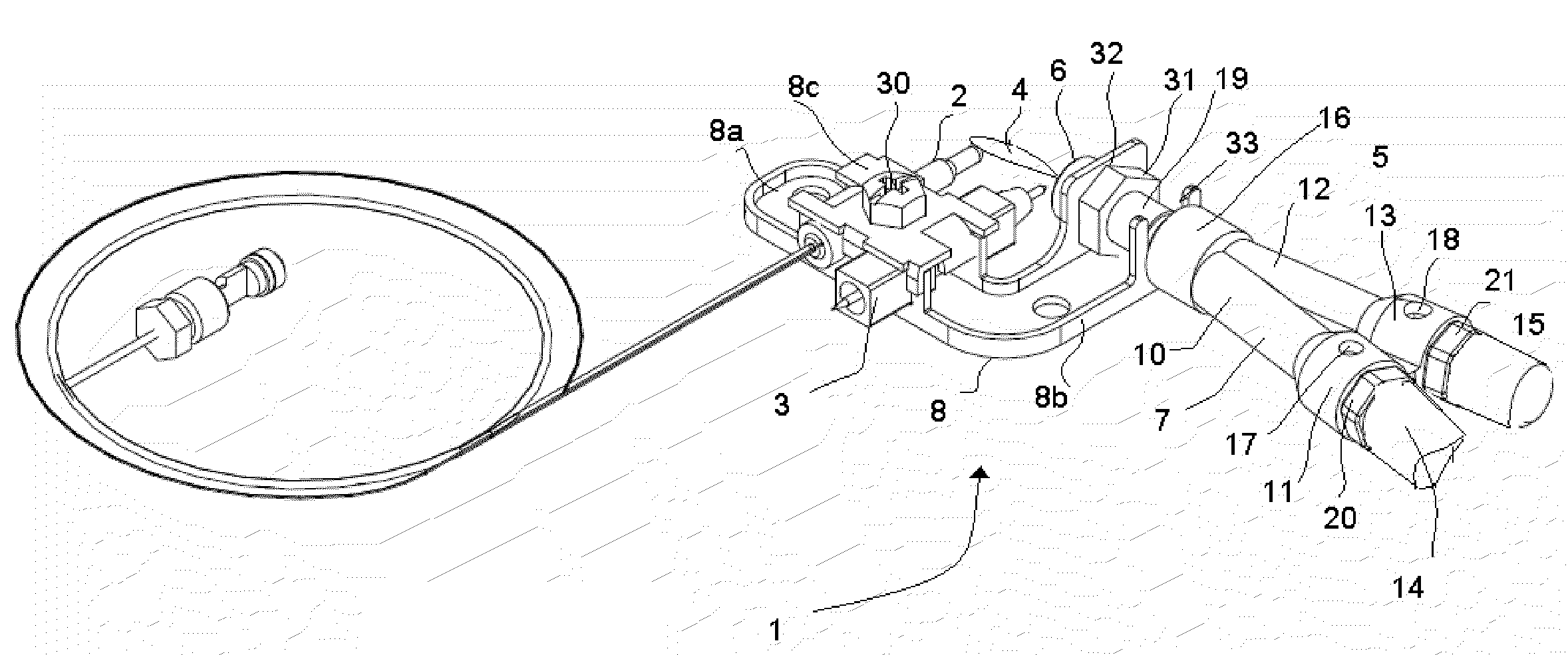
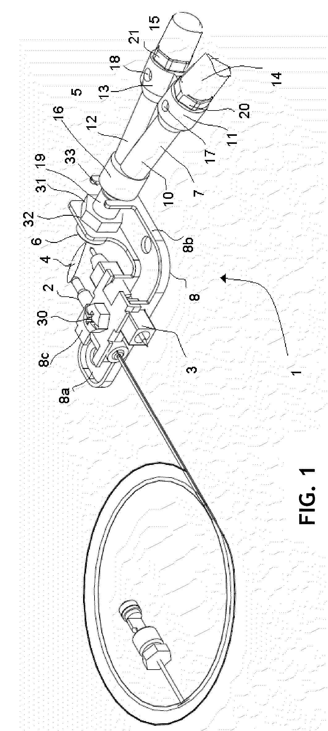
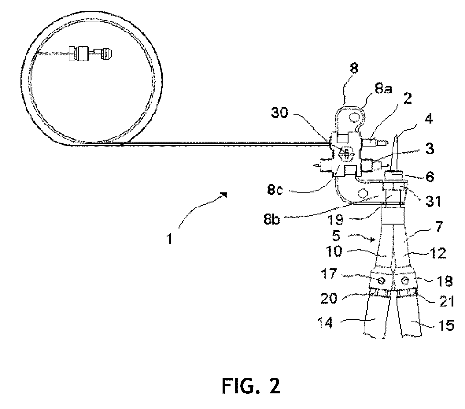
[0015]With reference to FIGS. 1 to 3, a pilot burner 1 adapted to household heating appliances, such as stoves and water heaters, is shown that comprises a safety thermocouple 2 that is connected to a control valve not shown in the figures, an igniter 3 (e.g., spark generator) that is connected to an ignition switch not shown in the figures, and an injector 5 that is supplied with a first combustible fluid or a second combustible fluid and which includes a nozzle 6 through which it supplies a pilot flame 4 that heats the thermocouple 2, with the result that the thermocouple 2 continues to power the control valve to keep it open and therefore keep the passage of the first combustible fluid or the second combustible fluid to the injector 5 open.

[0016]In one embodiment, the injector 5, shown in detail in FIG. 4, comprises a combustion body 7 preferably made of injected aluminium, which is connected by means of a first connector 20 to a first supply pipe 14 that supplies the first combu...


PUM


Abstract

A multiple gas pilot burner assembly for a household heating appliance. The pilot burner includes an injector having a first conduit for receiving a flow of a first combustible fluid, a second conduit for receiving a flow of a second combustible fluid and a third conduit connected to and in fluid communication with the first and second conduits which is configured to receive the flow of the first combustible fluid from the first conduit or the flow of the second combustible fluid from the second conduit. A single nozzle at the outlet of the third conduit is provided for supplying a pilot flame. The assembly also includes a single flame igniter positioned to cause an ignition of the pilot flame at the nozzle and also a single thermocouple positioned to be heated by the pilot flame and to generate an electrical current when heated.

Description

CROSS-REFERENCE TO RELATED APPLICATIONS[0001]This application claims priority to Spanish Patent Application No. U200800992, filed May 12, 2008.TECHNICAL FIELD[0002]The present invention relates to a pilot burner with adapted to multiple or dual household heating appliances that may be supplied with natural gas (NG) or liquefied petroleum gas (LPG), such as stoves or water heaters, preferably non-ventilated. BACKGROUND[0003]There are known household heating appliances in the prior art that include pilot burners with oxygen depletion sensors. The level of oxygen in a typical ventilated room is generally around 21%, which allows the combustion of a combustible fluid to take place correctly. Problems arise when the level of oxygen falls below 18%, a situation that may occur in non-ventilated household heating appliances and which leads to poor combustion of the combustible fluid, carbon monoxide thus being generated and causing a corresponding danger to the user. To prevent the problem,...

Claims


Application Information

Patent Timeline
IPC IPC(8): F23Q7/00F23N5/10
CPCF23N5/242F23N2029/02F23Q9/04F23N2037/02F23N2037/08F23N2031/08F23N2229/02F23N2231/08F23N2237/02F23N2237/08Y10T137/1516
Inventor ANTXIA URIBETXEBARRIA, JOSE JOAQUINMATEOS MARTIN, RUBEN
Owner COPRECITEC
Why Eureka
Try Eureka