
Method for Constructing Network Topology, and Streaming Delivery System

a delivery system and network topology technology, applied in the field of computer network technologies, can solve the problems of network only rejecting services, unable to fully meet all abrupt rises of user requests, and large investments in edge nodes, so as to reduce the load of es-p content servers, improve quality, and increase bandwidth

Active Publication Date: 2009-11-12
HUAWEI TECH CO LTD
View PDF11 Cites 34 Cited by
  • Summary
  • Abstract
  • Description
  • Claims
  • Application Information

AI Technical Summary

Benefits of technology

[0011]Disclosed embodiments provide a method for constructing a network topology and a streaming delivery system to increase the streaming transmission rate and improve the playing quality compared with the conventional art.
[0040]The disclosed embodiments may transmit a part of streaming data by constructing a network topology between clients, and reduce the load of the ES-P content server. Therefore, compared with the P2P streaming live networks, the embodiments provide live services with larger bandwidths and better quality. In addition, the streaming delivery network according to some embodiments avoids the impacts of long distance data transmission between the nodes on the backbone network during the P2P live cast, and limits the data transmission between the nodes to the network edge. This facilitates the mutual-aid downloading of streaming data between the nodes and recovers the network topology quickly when the nodes exit, reducing network disturbances effectively.

Problems solved by technology

Thus, for the CDN / MDN structure in the conventional art, huge investments are required in an edge node.
Because service requests of a user are indefinite, even though the system capability of the edge node is increased, it is difficult to fully meet all abrupt rises of user requests.
As a result, once the number of concurrent user requests in an area exceeds the maximum capacity of the network, the network may only reject the service.
The inventor finds that the P2P streaming software system in the conventional art does not appear to consider geographic issues, which may result in a large volume of traffic across backbone networks.
Moreover, because the scheduling module does not record the topology relations of node networks and does not provide unified resource scheduling, data delivery basically relies on the mutual aid of nodes.
Therefore, channel switching may take a long time and programs of large streams may be difficult to support.
In addition, the unsteady nodes and the best-effort help mode may also result in unstable playing of programs.
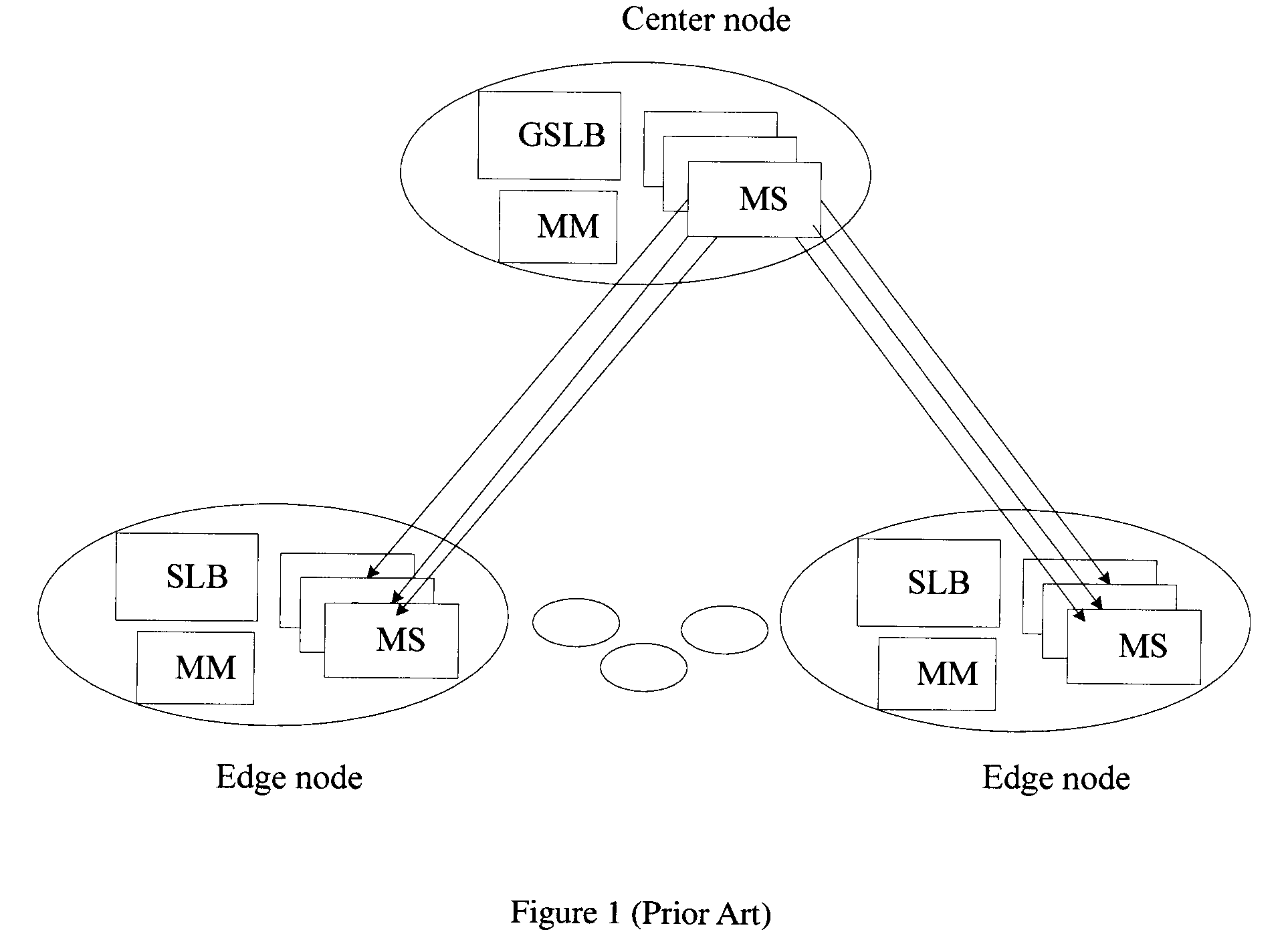
In conclusion, the streaming system based on client / server mode in the conventional art causes a heavy load on the MS, whether in center mode or center-edge distribution mode.
For streaming live services based on P2P technology, because the server has limited resources and may provide only few streaming data and most of nodes rely on the upload capabilities of other nodes to watch video programs, it is difficult to guarantee the quality of service (QoS).
In addition, due to limitation of upload capabilities, the P2P technology cannot provide live programs at a high bit rate.

Method used


Image

  • Method for Constructing Network Topology, and Streaming Delivery System
  • Method for Constructing Network Topology, and Streaming Delivery System
  • Method for Constructing Network Topology, and Streaming Delivery System

Examples


Embodiment Construction

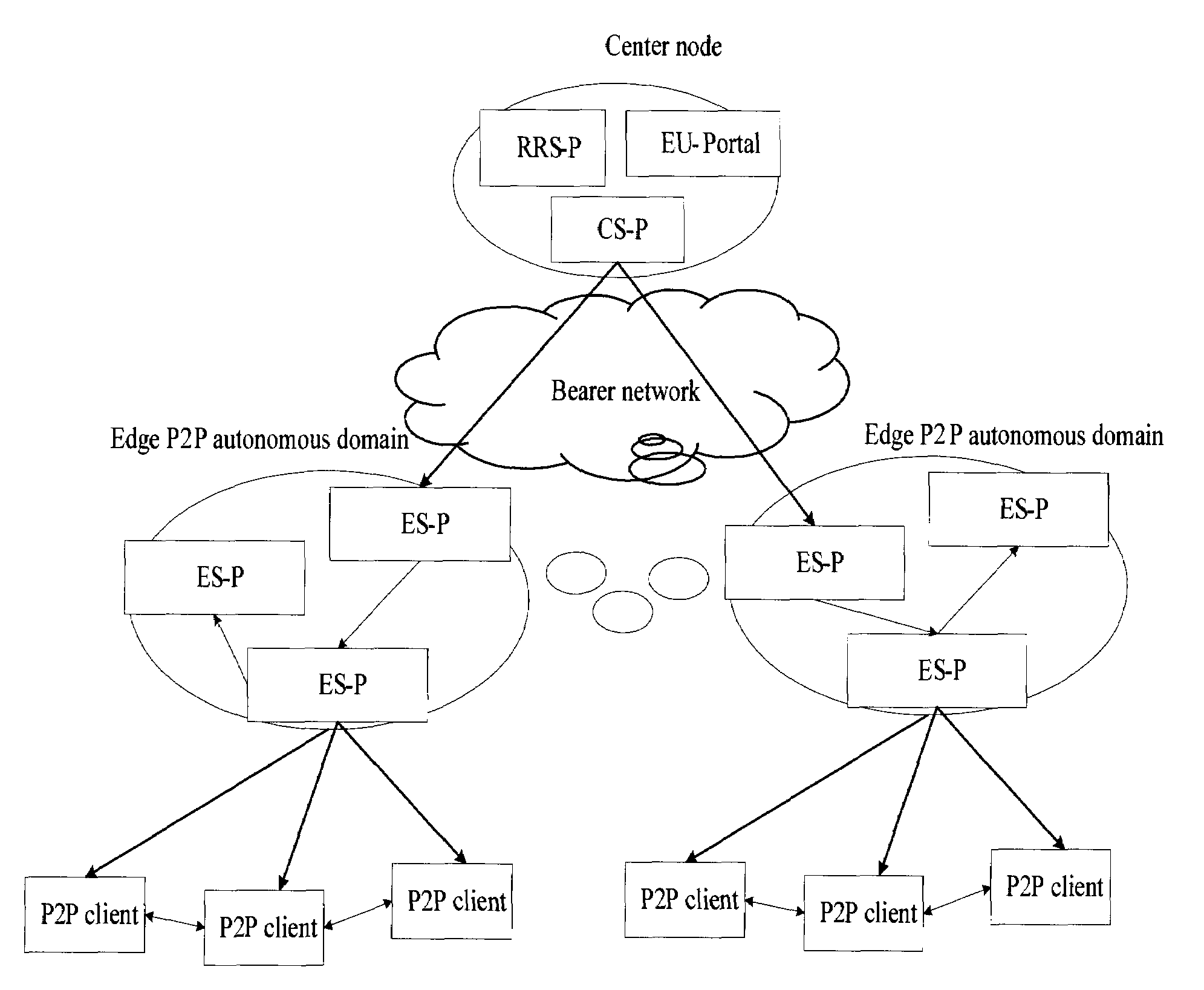
[0051]Consistent with some embodiments, a network topology between clients is constructed, so that a client may obtain a part of streaming data (furthermore, the rest of streaming data may still be requested from a content server) from other clients. This lowers the load requirements for the server without affecting the QoS. A network topology is constructed between the clients to limit the connection between the clients in a partial network in some embodiments, thus guaranteeing the transmission quality and reducing the traffic across networks.

[0052]The following describes major principles, implementation modes, and benefits of the technical solution according to some embodiments with reference to the accompanying drawings.

[0053]The structure of a streaming delivery system according to some embodiments is shown in FIG. 2. The streaming delivery system includes: an end user portal (EU-Portal), a center server that supports P2P technology (CS-P), a request scheduling server that supp...


PUM


Abstract

A method for constructing a network topology is applied in a streaming delivery system. The streaming delivery system includes: a center server (CS-P), an edge server (ES-P), a request scheduling server (RRS-P), and a client. The disclosed embodiments utilizes the upload capabilities of the client to transmit a part of streaming data, thus consuming fewer center server resources. By constructing the network topology, the disclosed embodiments enable the client to obtain a part of streaming data from other clients, reduces the load capability requirements for the server, and ensures that a streaming delivery network may provide streaming live services with higher bandwidths and better quality.

Description

CROSS-REFERENCE TO RELATED APPLICATION[0001]This application is a continuation of International Application No. PCT / CN2008 / 071072, filed on May 23, 2008, titled “A METHOD FOR CLIENT NODE NETWORK TOPOLOGY CONSTRUCTION AND A SYSTEM FOR STREAM MEDIA DELIVERY”, which claims the priority of CN application No. 200710110570.6, filed on Jun. 5, 2007, titled “A METHOD FOR CLIENT NODE NETWORK TOPOLOGY CONSTRUCTION AND A SYSTEM FOR STREAM MEDIA DELIVERY”, the entire contents of all of which are incorporated herein by reference.FIELD OF THE DISCLOSURE[0002]The present disclosure relates to computer network technologies, and in particular, to a method for constructing a network topology, a streaming delivery system, and a method for system-related entities and clients to join the streaming delivery system.BACKGROUND OF THE DISCLOSURE[0003]A content / media delivery network (CDN / MDN) has emerged in the conventional art, delivering website contents from a source node to an edge node closest to a use...

Claims


Application Information

Patent Timeline
IPC IPC(8): G06F15/16
CPCH04L12/18H04L45/00H04L65/4069H04L67/1046H04L67/104H04L67/2842H04L65/80H04L65/61H04L67/568
Inventor WANG, ZHIBINGYAN, ZHEFENGCHEN, HAOHUADUI, JIYINGLI, YAOHUIWEI, JIAHAOXUE, CHUANSONG
Owner HUAWEI TECH CO LTD
Learn More