Susceptor positioning and supporting device of vacuum apparatus

a technology of supporting device and sucker, which is applied in the direction of coating, chemical vapor deposition coating, coating process, etc., can solve the problems of unnecessarily increasing hardware and power consumption, affecting the uniformity of large thin-film deposition process, and affecting the quality of thin-film, so as to reduce edge drooping and enhance the uniformity of large-scale thin-film deposition process , the effect of uniform plasma density

Inactive Publication Date: 2009-11-19
IND TECH RES INST
View PDF6 Cites 7 Cited by
  • Summary
  • Abstract
  • Description
  • Claims
  • Application Information

AI Technical Summary

Benefits of technology

[0022]In summary, the susceptor positioning and supporting device of the vacuum apparatus according to the present invention employs a lateral positioning and supporting mechanism that is disposed symmetrically around the center axis of the second perforation of the elevator platform. With the susceptor penetrating the second perforation and the sides of the susceptor being clamped by the lateral positioning and supporting mechanism, the susceptor can thus be prevented from slanting inside the chamber. The mechanism and the susceptor also form a closed beam support structure that reduces edge drooping of large-sized susceptor, thereby achieving planarity for large-sized susceptors and uniformity for thin-film deposition. In addition, the actual position and stance of the susceptor can be monitored from outside of the chamber, in particular, in Capacitive Coupling Plasma (CCP) system application, the parallelism between two electrodes can be improved to obtain uniform plasma density. Therefore, the present invention enhances uniformity of large thin-film deposition processes for fabricating of TFT LCD and thin-film solar cell etc., thereby obtaining thin films with excellent quality.

Problems solved by technology

According to the prior art, although the bottom of the center shaft can be fixed in position, swaying and deflection is likely to happen to the susceptor during elevation.
Similarly, the quality of the thin film is degraded.
However, said patent only provides application for fixed process distance.
If the susceptor is also a heating device, cost of hardware and power consumption will be unnecessarily increased.
Furthermore, this prior art provides no solution for serious deformation at the ends of the cantilever susceptor under high temperature.
However, while supporting the susceptor by said plurality of support boards, this established technique is incapable of knowing whether the susceptor is evenly supported by each of the support boards, in other words, whether the susceptor is slanted.
As a result, the quality of thin film is still not assured.

Method used


Image

  • Susceptor positioning and supporting device of vacuum apparatus
  • Susceptor positioning and supporting device of vacuum apparatus
  • Susceptor positioning and supporting device of vacuum apparatus

Examples


first embodiment

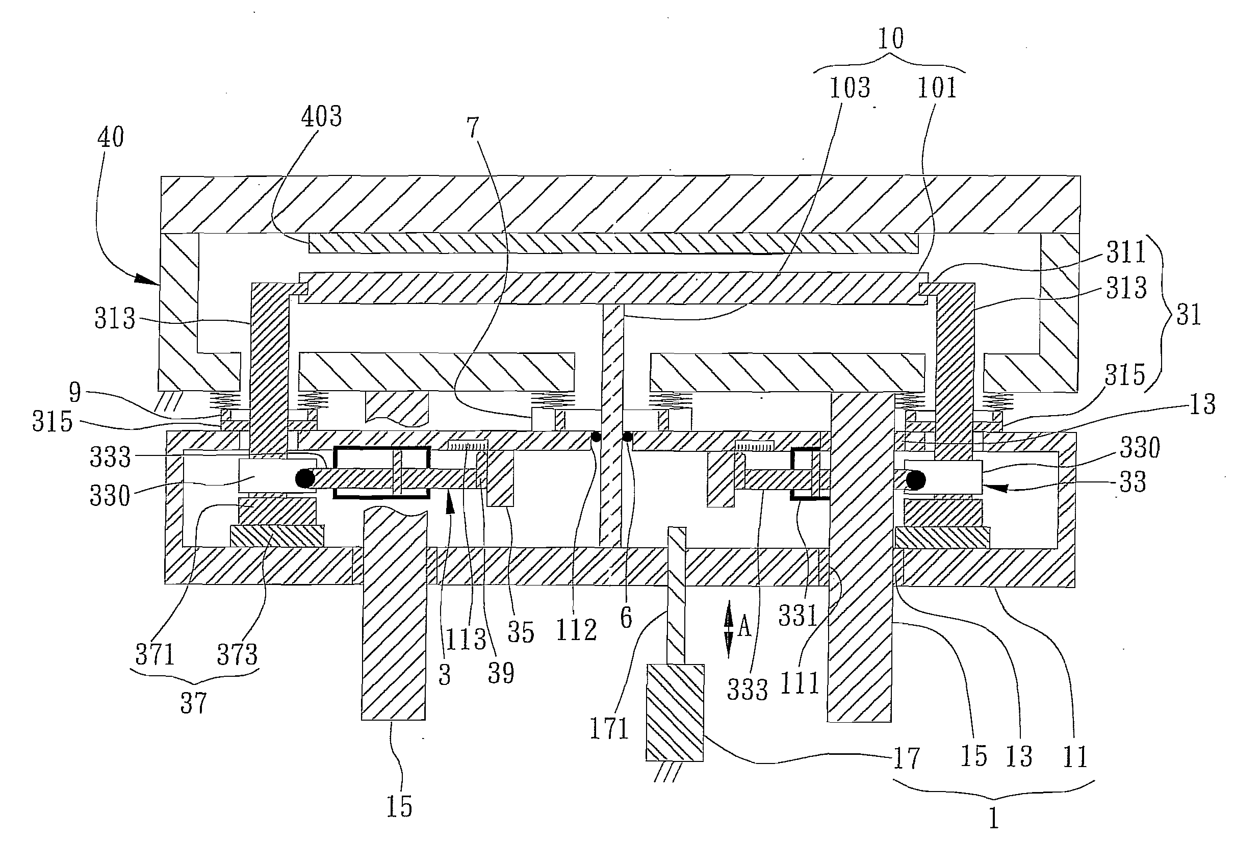
[0030]FIG. 2 is a diagram illustrating the susceptor positioning and supporting device for a vacuum apparatus of the present invention. As shown in the FIG. 2, the susceptor positioning and supporting device of the vacuum apparatus of the present embodiment is used for positioning and supporting a susceptor 10 in a thin-film deposition chamber 40 of the vacuum apparatus. The susceptor 10 is capable of moving up and down inside the thin-film deposition chamber 40, and it includes a substrate carrying part 101 for carrying a substrate (not shown), and a susceptor center shaft part 103 connected to the substrate carrying part 101. The center axis of the susceptor 10 is also the center axis of both the susceptor center shaft part 103 and the substrate carrying part 101. The thin-film deposition chamber 40 can be a vacuum thin-film deposition chamber with an upper electrode 403 disposed on the chamber cover thereof, but not limited thereto. The present invention is also applicable to oth...

second embodiment

[0055]Referring to FIG. 4A, which is a diagram illustrating the susceptor positioning and supporting device of the vacuum apparatus of the present invention, components that are the same as or similar to those in the first embodiment are designated by the same symbols and no detailed description will be given hereafter.

[0056]The difference between the first and second embodiments is in that the clamp claw part 311 includes an arc-shaped protruding part, and the side of the susceptor 10 has a corresponding arc-shaped sunken part. Accordingly, the arc-shaped protruding part of the clamp claw part 311 has a larger diameter, while the corresponding arc-shaped sunken part at clamped side of the substrate carrying part 101 has a smaller diameter, not necessarily forming a tightly clamp relationship at the substrate carrying part 101. Therefore, by providing lateral clamp force to maintain contact with the side of the substrate carrying part 101, the clamp claw part 311 is capable of suppo...

third embodiment

[0059]Referring to FIG. 4B, which illustrates the susceptor positioning and supporting device of the vacuum apparatus of the present invention, components that are the same as or similar to those in the previous embodiments are designated with same symbols and no detailed description will be given hereafter.

[0060]The present embodiment is different from the previous embodiments in that the clamp set motion is modified. For instance, the clamp set motion module is modified by providing a clamp set motion module that comprises a rotating shaft to replace said slide block and said slide track.

[0061]As shown in FIG. 4B, a clamp swaying structure is formed by using a rotating shaft 375 that couples the clamp main part 313 of the clamp set 31 to the elevator platform 11. In this embodiment, the clamp claw part 311 and substrate carrying part 101 can include corresponding arc-shaped protruding and sunken parts. Since the clamp set 31 and the susceptor 10 contact to form a closed beam struc...


PUM

PropertyMeasurementUnit
flexibleaaaaaaaaaa
lengthaaaaaaaaaa
sizesaaaaaaaaaa

Abstract

A susceptor positioning and supporting device of a vacuum apparatus for carrying and elevating a substrate in a vacuum apparatus chamber is provided. The device has a lateral positioning and supporting mechanism to perform clamping and positioning at a side of a susceptor, preventing the susceptor from slanting inside the vacuum apparatus chamber. The lateral positioning and supporting mechanism and the susceptor thereby forms a closed beam support mechanism capable of reducing load suspension deformation at the ends of the large susceptor. The device improves planarity of the large susceptor and the substrate, and in turn improves uniformity of a thin film deposited on the substrate.

Description

BACKGROUND OF THE INVENTION[0001]1. Field of the Invention[0002]This invention generally relates to a positioning and supporting technique, and more specifically, to a susceptor positioning and supporting device for carrying and elevating a substrate in a vacuum chamber.[0003]2. Description of Related Art[0004]Industries such as semiconductor, Thin-Film Transistor Liquid Crystal Display (TFT LCD), thin-film solar cell, etc. have many common features in techniques, materials, and equipment. As the sizes of electronic products are increasing, the areas of substrates for silicon thin-film solar cell modules, LCD TVs, for example, that are sent into thin-film deposition equipment for process are getting larger. Therefore, in any thin-film deposition equipment, whether for Chemical Vapor Deposition (CVD) or Physical Vapor Deposition (PVD), large-sized susceptor has become an essential element for carrying out large-size thin-film deposition processes.[0005]Particularly, when performing a...

Claims


Application Information

Patent Timeline
Patent Type & Authority Applications(United States)
IPC IPC(8): C23C16/00
CPCC23C16/4586H01L21/68792H01L21/68785
Inventor DU, CHEN-CHUNGLIANG, MUH-WANGWU, CHING-HUEICHIANG, MING-TUNG
Owner IND TECH RES INST
Why Eureka
Try Eureka