Electromechanical device and electrical device with the electromechanical device

a technology of electromechanical devices and electrical devices, which is applied in the direction of electrical devices, electrostrictive/piezoelectric relays, waveguide devices, etc., can solve the problems of reducing reliability of electromechanical devices, unintentionally driving movable electrodes by electrostatic force, and generating potential differences between movable electrodes and drive electrodes, etc., to achieve high reliability and reduce device size and cost.

Inactive Publication Date: 2009-11-19
PANASONIC CORP
View PDF4 Cites 3 Cited by
  • Summary
  • Abstract
  • Description
  • Claims
  • Application Information

AI Technical Summary

Benefits of technology

[0011]The present invention is directed to solving the foregoing problem of the related art, and an object of the invention is to provide high reliability during high power input to an electromechanical device while also reducing device size and cost.

Problems solved by technology

However, when a strong signal is input to the electromechanical device, a potential difference is produced between the movable electrode and the drive electrode, and a problem known as self-actuation in which the movable electrode is unintentionally driven automatically by the electrostatic force occurs.
Self-actuation can cause such problems as structural failure due to operational errors or a strong drive force, or make it difficult for electrodes that have made contact to separate, and thus is a cause of reduced reliability in electromechanical devices.
This construction requires a solid state component, thus increasing both size and cost as a result of the increased number of components.

Method used


Image

  • Electromechanical device and electrical device with the electromechanical device
  • Electromechanical device and electrical device with the electromechanical device
  • Electromechanical device and electrical device with the electromechanical device

Examples


embodiment 1

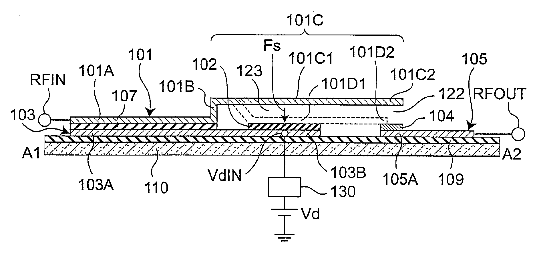
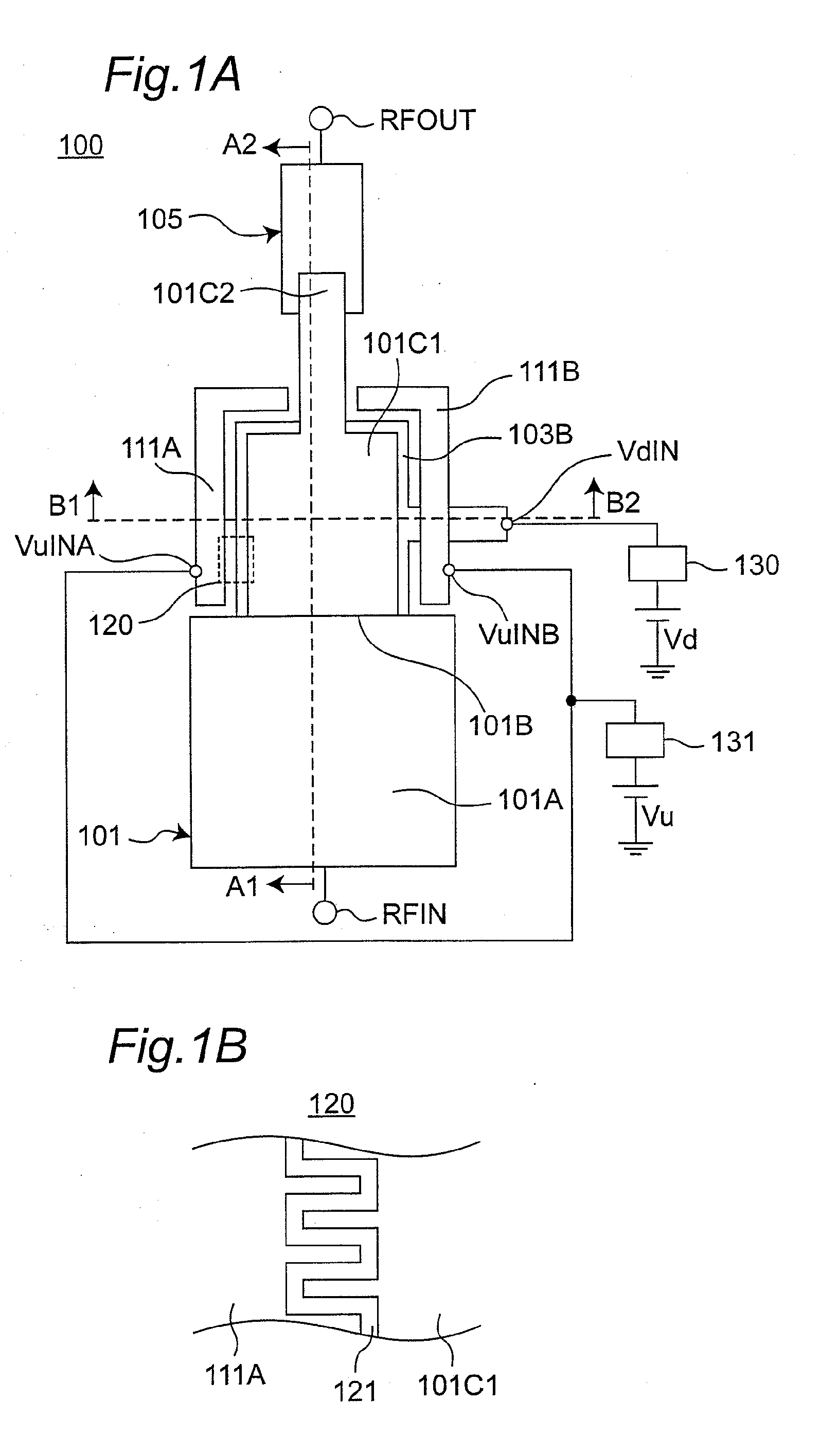
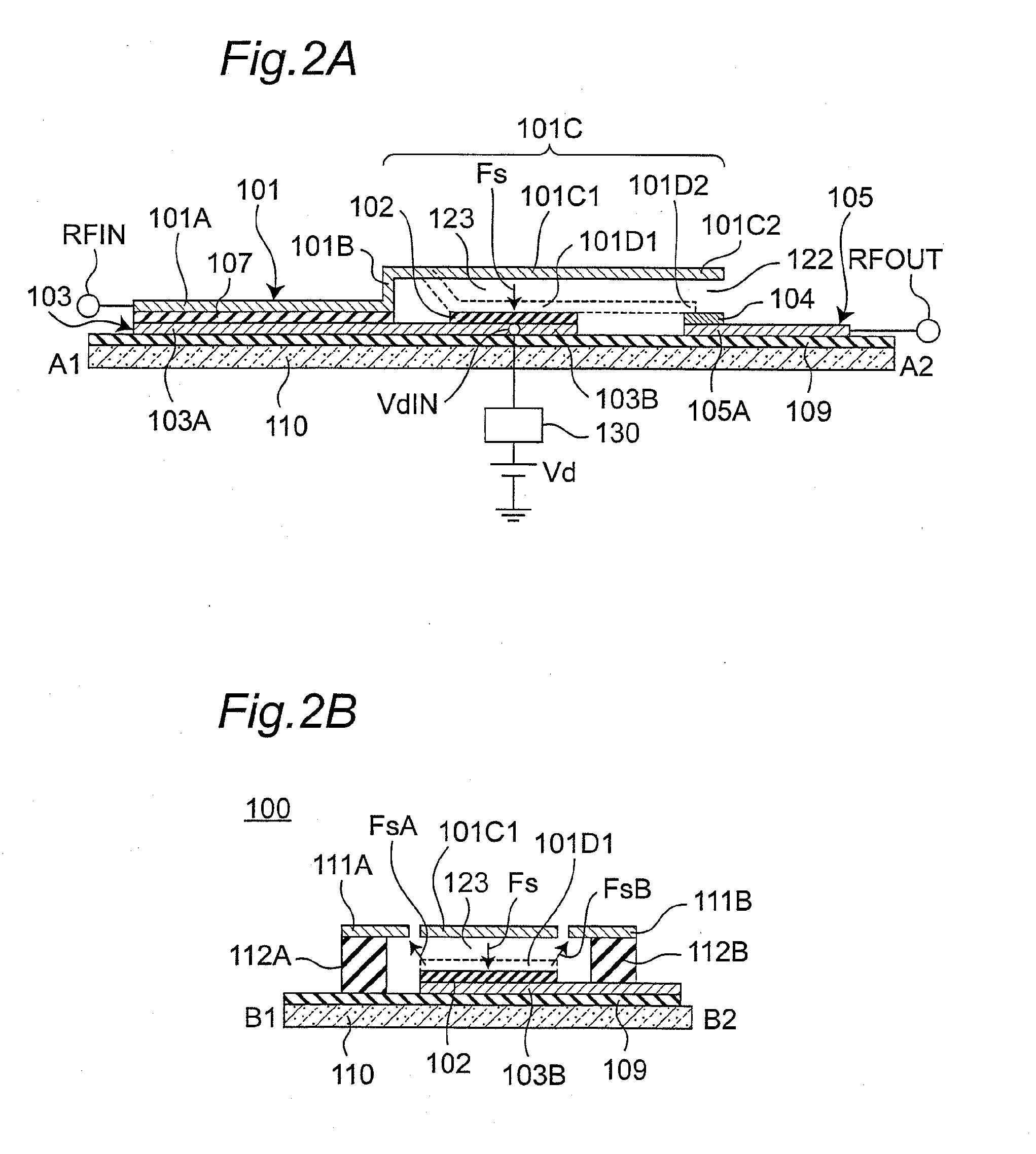
[0035]FIG. 1A is a plan view showing the configuration of an electromechanical device 100 according to a preferred embodiment of the invention, and FIG. 1B is a schematically enlarged view of the partial area 120 in FIG. 1A. FIG. 2A is a section view showing section A1-A2 in FIG. 1A, and FIG. 2B is a section view showing section B1-B2 in FIG. 1A.

[0036]As shown in FIG. 1A to FIG. 2B, the electromechanical device 100 has a substrate 110, a dielectric layer 107, a dielectric layer 109, a signal electrode 105, a contact 104, a movable electrode 101, a drive electrode 103, a dielectric layer 102, fixed comb electrodes 111A and 111B, and support parts 112A and 112B. The substrate 110 is typically a semiconductor substrate made of a semiconductor material. The dielectric layer 109 is formed on the substrate 110, constituting an isolation membrane between layers.

[0037]The movable electrode 101 bends at a movable electrode bending part 101B, and includes a movable electrode fixing part 101A ...


PUM


Abstract

When a high power signal is input to an electromechanical device, electrostatic force can automatically and unintentionally drive the movable electrode. A high reliability electromechanical device that prevents this is achieved. The electromechanical device of the invention is an electromechanical device formed on a substrate, and having a signal electrode and a drive electrode formed across a gap from a movable electrode. Applying an attraction force between the movable electrode and the drive electrode enables the movable electrode to contact the signal electrode. A high electrostatic capacitance is formed by disposing the movable electrode and drive electrode in opposition with a dielectric layer therebetween on the RF signal input port side. As a result, the potential difference between the movable electrode and drive electrode is reduced even when a high power signal is input, and a high reliability electromechanical device can be achieved.

Description

BACKGROUND OF THE INVENTION[0001]1. Field of Invention[0002]The present invention relates to an electrically driven electromechanical device, and relates more particularly to an electromechanical device and an electrical device with the electromechanical device.[0003]2. Description of Related Art[0004]Electromechanical devices are used in many different fields, including telecommunications, optics, acceleration sensors, and biotechnology, and can be used for switches, filters, and other devices particularly in wireless terminal devices. As wireless terminal devices and other data communication devices have come into widespread use, small wireless terminal devices that are compatible with different communication systems have become desirable. Because the number of passive devices such as switches that are used inside the terminal housing increases in such multimode terminal devices, reducing the size of the passive devices is desirable.[0005]Radio frequency MEMS (RF-MEMS) switches ma...

Claims


Application Information

Patent Timeline
Patent Type & Authority Applications(United States)
IPC IPC(8): H01H59/00
CPCB81B3/0086H01P1/127H01H59/0009
Inventor NAITO, YASUYUKI
Owner PANASONIC CORP
Why Eureka
Try Eureka