Method of fabricating small dimensioned lens elements and lens arrays using surface tension effects

Active Publication Date: 2009-11-19
FOR NAT RES INITIATIVES
View PDF3 Cites 6 Cited by
  • Summary
  • Abstract
  • Description
  • Claims
  • Application Information

AI Technical Summary

Benefits of technology

[0017]These and other objectives are realized in the present invention by using a novel and very flexible fabrication methodology combined with innovative design improvements. The present invention results from surface tension effects that are common when two different materials come into contact and one of the materials is heated to above its melting point.
[0018]The present invention relates to lenses, and, more particularly, to a method of making lens elements or lens arrays having dimensions ranging from a few centimeters down to the micro-scale or nano-scale using the surface tension of the lens material in a molten state to allow the curved shape of the lens to be precisely defined. The method of the present invention has useful application in the fabrication of lens elements and lens arrays ou

Problems solved by technology

These micro-lenses and micro-lens arrays are typically made using specialized semiconductor processes to allow the implementation of lens profiles with performance far inferior to that of similar types of lenses made at the macro-scale.
First, these methods involve fabrication processes that are extremely difficult to control or to obtain reproducible results from batch to batch.
As a result, the yield of these methods can be quite low with the resultant consequence of higher cost components.
Second, most of these processes result in some significant distortions of the lens shapes with negative consequences for the performance of the lenses or lens arrays.
Third, the surface smoothness of RIE etched or FIB machined surfaces are typically very rough (e.g., more than a few nanometers) which degrade the performance of the lens elements due to photon scattering as well as other effects.
Fourth, the use of a FIB tool to make lenses is an extremely slow process, is performed on a very expensive tool, and is, therefore, a

Method used


Image

  • Method of fabricating small dimensioned lens elements and lens arrays using surface tension effects
  • Method of fabricating small dimensioned lens elements and lens arrays using surface tension effects
  • Method of fabricating small dimensioned lens elements and lens arrays using surface tension effects

Examples


Example

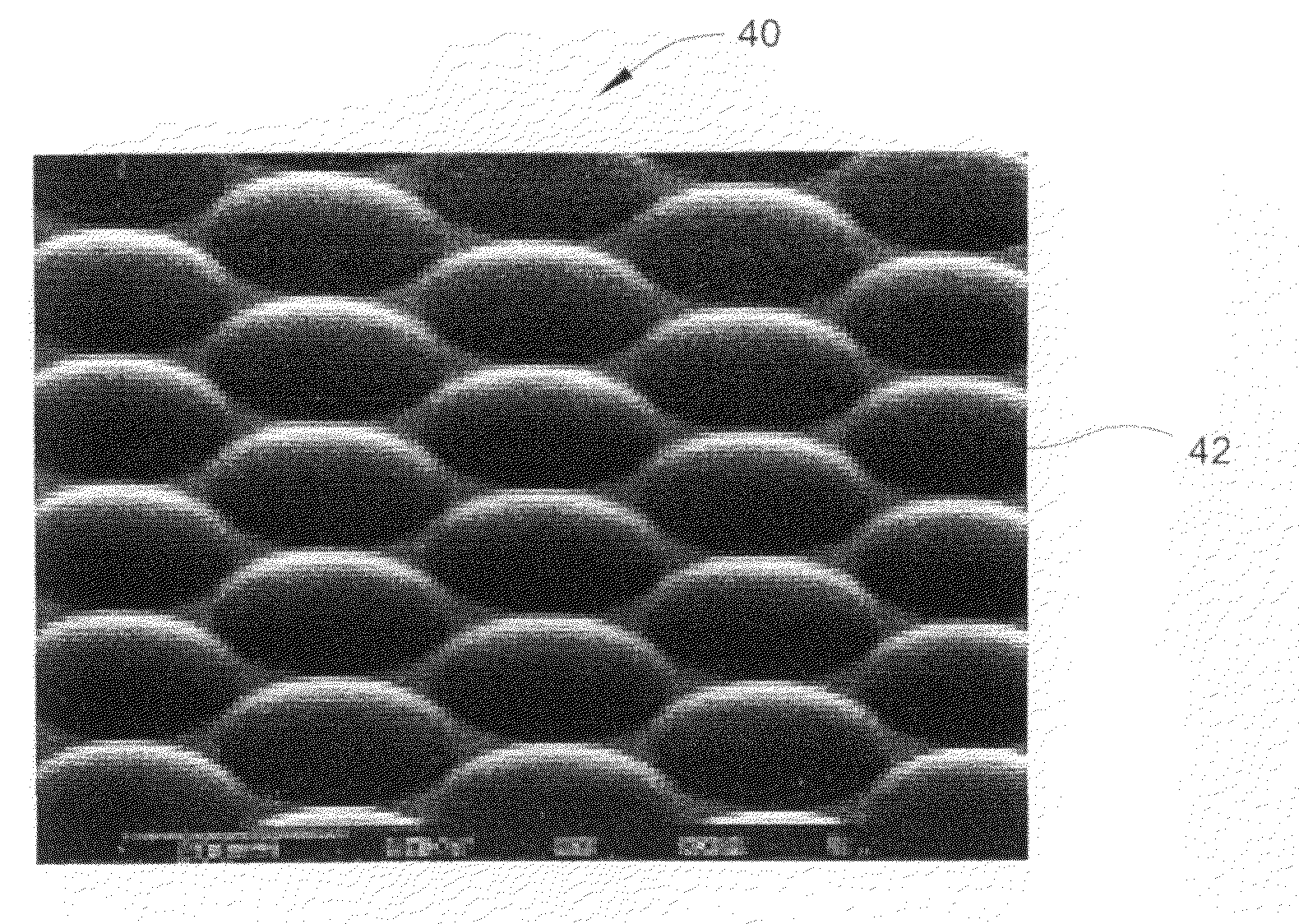
[0029]The present invention is directed to a method of fabricating lens elements and lens arrays using the surface tension of the lens material(s) to develop a desired lens surface contour or shape and thereby make a high performance refractive lens. A variety of different types of lenses can be fabricated using the method of the present invention, including concave or convex lenses, as well as many others types of lenses. Additionally, lens arrays composed of a multiplicity of lens elements can also be made using the method of the present invention. Furthermore, the method of the present invention allows the fabrication of lens elements and lens arrays having an unprecedented small lateral lens diameter, as well as extremely smooth surface finishes, which is not possible with existing methods of lens and lens array fabrication. The present invention also provides an extremely low cost and relatively simple production method for lens elements and lens arrays, as compared to existing...


PUM


Abstract

A method is disclosed of implementing lens elements or lens arrays having dimensions ranging from a few centimeters down to the micro-scale or nano-scale using the surface tension of the lens material in a molten state to allow the curved shape of the lens to be precisely defined. The method has useful application in the fabrication of lens elements and lens arrays out of a large variety of material types, including elemental materials, as well as compound materials and alloys. The method also allows the implementation of lenses having far superior surface smoothness compared to other approaches, as well as very accurate lens shapes. The method allows the making of high quality lenses and lens arrays, wherein the diameter of the lenses are on the order of a few microns or less. Convex, concave, plano-convex, plano-concave, compound lenses, and many other types of lens shapes can be implemented using the method of the present invention.

Description

CROSS-REFERENCE TO RELATED APPLICATION[0001]This application claims the benefit of Provisional Application No. 61 / 071,777, filed May 16, 2008, the entire contents of which are hereby incorporated by reference in this application.FIELD OF INVENTION[0002]The present invention relates to lenses, and, more particularly, to a method of implementing lens elements or lens arrays having dimensions ranging from a few centimeters down to the micro- or nano-scale using the surface tension of the lens material in a molten state to allow the curved shape of the lens to be precisely defined.BACKGROUND OF THE INVENTION[0003]The making of lenses and lens arrays is an extremely important part of modern technology, particularly in optics and photonics. Lenses at the macro-scale (i.e., a few centimeters in diameter or larger) can be made using a variety of methods, including various machining methods (e.g., diamond turning, etc.), molding, embossing, etc., to obtain adequately high levels of precision...

Claims


Application Information

Patent Timeline
IPC IPC(8): B29D11/00
CPCB29D11/00365G02B3/0075G02B3/0018
Inventor HUFF, MICHAEL A.
Owner FOR NAT RES INITIATIVES
Why Eureka
Try Eureka