
Optical coherence tomographic imaging device and imaging method of optical coherence tomographic image

a tomographic imaging and optical coherence technology, applied in the field of optical coherence tomographic imaging devices and optical coherence tomographic imaging methods, can solve the problems of difficult to keep the examined eye still, difficult to pass through the measuring beam through the pupil, and the reliability of the tomographic image becomes relatively low, so as to achieve the effect of suppressing influen

Inactive Publication Date: 2009-11-19
CANON KK
View PDF7 Cites 34 Cited by
  • Summary
  • Abstract
  • Description
  • Claims
  • Application Information

AI Technical Summary

Benefits of technology

[0028]In view of the above described problem, the present invention has an object to provide an optical tomographic imaging device and an imaging method of an optical tomographic image which suppress influence when a measuring beam is truncated by an iris and can ensure reliability of an tomographic image to be acquired, especially when imaging the tomographic image of the retina in the eyeground of an examined eye.
[0036]According to the present invention, an optical tomographic imaging device, which suppresses influence in the case where a measuring beam is truncated by an iris and can ensure reliability of the tomographic image which is acquired, when imaging a tomographic image of a retina in an eyeground of an examined eye by an OCT device, and an optical tomographic image can be realized.

Problems solved by technology

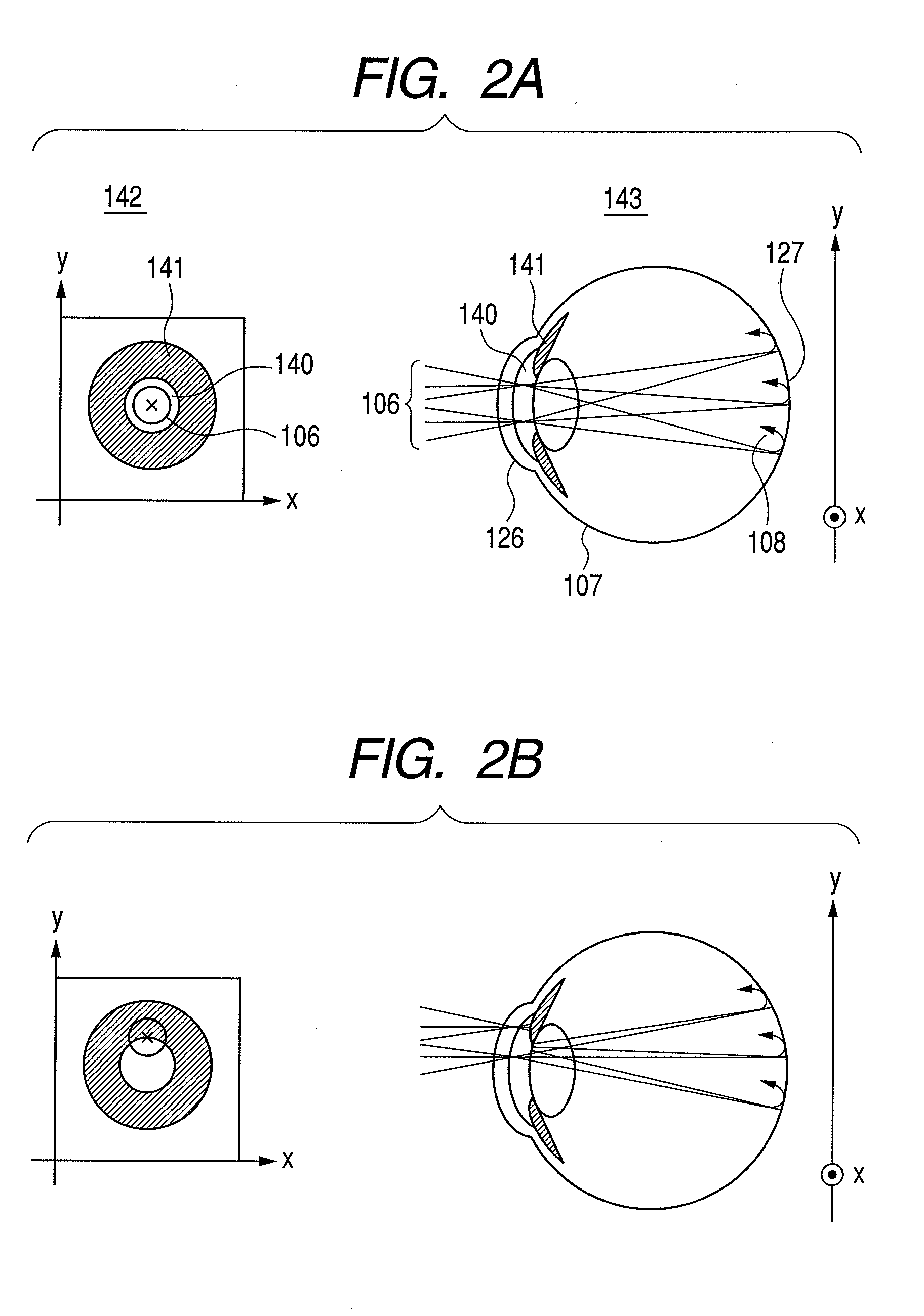
When ophthalmologic diagnosis of a retina is performed by the OCT device, it is sometimes difficult for the measuring beam to pass through a pupil without being truncated by an iris and form an image at a desired position of the retina for the reason that it is difficult to keep the examined eye standstill.
Thus, reliability of the tomographic image becomes relatively low.
However, in the device in Japanese Patent Application Laid-Open No. 2002-174769 of the prior art described above, the problem as described above which occurs when the measuring beam is truncated by the iris in the OCT device is not taken into consideration.
However, the above described problem is not considered at all.

Method used


Image

  • Optical coherence tomographic imaging device and imaging method of optical coherence tomographic image
  • Optical coherence tomographic imaging device and imaging method of optical coherence tomographic image
  • Optical coherence tomographic imaging device and imaging method of optical coherence tomographic image

Examples


embodiment 1

[0068]In embodiment 1, an OCT device to which the present invention is applied will be described.

[0069]In the present embodiment, TD-OCT (Time Domain OCT) which specially acquires a tomographic image of a retina of an eye will be described.

[0070]However, the present invention can be applied to not only such TD-OCT but also to FD-OCT (Fourier Domain OCT).

[0071]First, a schematic configuration of an entire optical system of the OCT device in the present embodiment will be described.

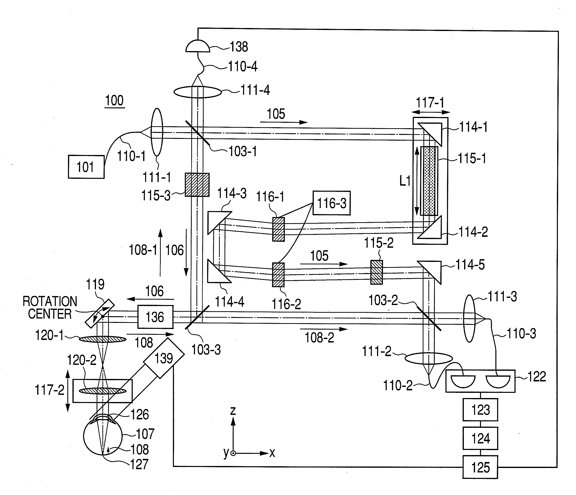
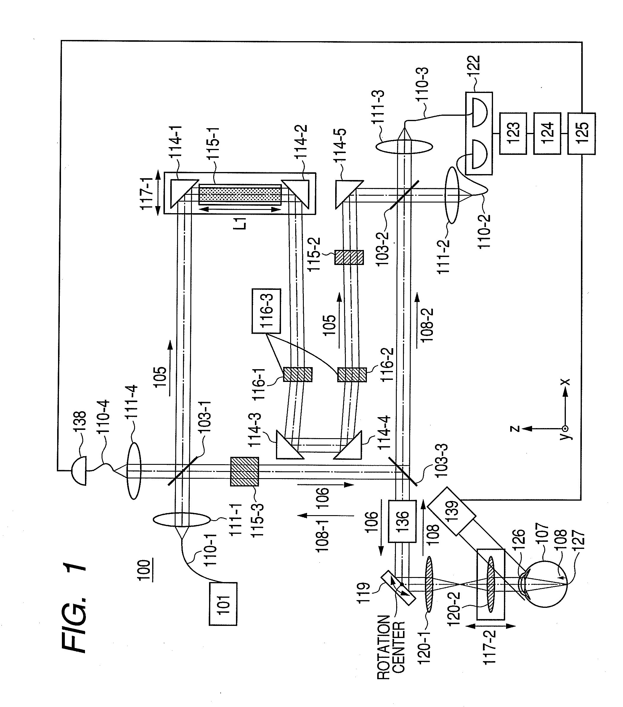
[0072]FIG. 1 illustrates a view about the schematic configuration of the entire optical system of the OCT device in the present embodiment.

[0073]In FIG. 1, in an OCT device 100, a light source 101, a beam splitter 103, a reference beam 105, a measuring beam 106, an eye 107, a return beam 108, a single mode fiber 110, lenses 111 and 120, and a mirror 114 are set.

[0074]In the OCT device 100, dispersion compensating glass 115, an acousto-optic modulating device 116, an electric stage 117, an XY scanner 119, a ...

embodiment 2

[0175]In embodiment 2, a configuration example of configuring any of the optical paths shown in embodiment 1 by an optical fiber will be described.

[0176]FIG. 5 illustrates a view describing a schematic configuration of an entire optical system of an OCT device in the present embodiment.

[0177]In FIG. 5, the same reference numerals and characters are assigned to the same or corresponding configurations as or to the configurations of embodiment 1 shown in FIG. 1, and therefore, description of the redundant configurations will be omitted.

[0178]In FIG. 5, an OCT device 200, a single-mode fiber 130 and an optical coupler 131 are set.

[0179]In the present embodiment, the OCT device 200 is used as the device for acquiring a tomographic image of the retina 127 of the eye 107 in an examined eye.

[0180]In the present embodiment, the device is made compact by configuring a part of the optical system by using an optical fiber.

[0181]Except for use of the optical fiber, the present embodiment includ...


PUM


Abstract

An optical tomographic imaging device and the like which suppress influence in the case of a measuring beam being truncated by an iris, and can ensure reliability of a tomographic image which is acquired, when imaging the tomographic image of a retina in an eyeground of an examined eye. An optical tomographic imaging device is configured to have an observation unit observing a state of irradiating an examined object with the measuring beam, and imaging a state of the measuring beam being incident on the examined object as an observation image, a recording unit recording the observation image by linking the observation image with a tomographic image by the optical tomographic imaging device, and an evaluating unit evaluating reliability of the tomographic image which is linked with the observation image based on the observation image imaged in the observation unit.

Description

BACKGROUND OF THE INVENTION[0001]1. Field of the Invention[0002]The present invention relates to an optical coherence tomographic imaging device and an imaging method of an optical coherence tomographic image, and particularly relates to an optical coherence tomographic imaging device and an imaging method of an optical coherence tomographic image used in ophthalmic diagnosis and treatment, and the like.[0003]2. Description of the Related Art[0004]Various ophthalmologic apparatuses using optical devices are used at present.[0005]For example, as optical devices for observing eyes, various kinds of devices such as an anterior ocular segment photographing device, a fundus camera, and a confocal scanning laser ophthalmoscope (Scanning Laser Ophthalmoscope: SLO) are used.[0006]Among them, an optical coherence tomographic imaging device by optical coherence tomography (OCT: Optical Coherence Tomography) using multiwavelength light wave coherence can obtain a tomographic image of a specime...

Claims


Application Information

Patent Timeline
Patent Type & Authority Applications(United States)
IPC IPC(8): H05G1/60
CPCA61B3/102
Inventor HIROSE, FUTOSHIMIYATA, KAZUHIDEYAMADA, KAZURO
Owner CANON KK
Learn More