Hydraulic circuit, energy recovery device, and hydraulic circuit for work machine

a technology of energy recovery device and hydraulic circuit, which is applied in the direction of fluid coupling, servomotor, coupling, etc., can solve the problems of inability to feed a sufficient amount of supplementary hydraulic fluid, limited application of pump motor and motor generator combination, and affecting the stable functioning of the boom cylinder, etc., to achieve the effect of improving the working efficiency, high flow rate of hydraulic fluid, and increasing the speed of the boom raising action

Inactive Publication Date: 2009-11-26
CATEPILLAR SARL
View PDF3 Cites 70 Cited by
  • Summary
  • Abstract
  • Description
  • Claims
  • Application Information

AI Technical Summary

Benefits of technology

[0023]According to the present invention, hydraulic fluid that would otherwise be fed from the first main pump to the bucket cylinder can be fed to the boom cylinder through the solenoid valve between bucket and boom; hydraulic fluid that would otherwise be fed from the second main pump to the stick cylinder can be fed to the head-side of the boom cylinder through the solenoid valve between stick and boom; and hydraulic fluid can be fed from the boom assist pump to the boom cylinder. By thus feeding a significantly high flow rate of hydraulic fluid to the head side of the boom cylinder, it is possible to increase the speed of boom raising action and improve working efficiency. Furthermore, given hydraulic pressures respectively required by the bucket cylinder and the stick cylinder can be ensured by shifting the solenoid valves to their respective positions for interrupting the flow of fluid.
[0024]According to the present invention, when the straight travel valve is at the straight travel position, equally divided volume of hydraulic fluid is fed from either the first main pump or the second main pump to the two travel motors, thereby enabling the work machine to travel straight. When the straight travel va...

Problems solved by technology

Therefore, when functioning as a hydraulic motor, the pump motor suddenly starts due to emergence of flow of return fluid from the boom cylinders and halts due to cessation of the return fluid, causing a shock.
As this load fluctuates depending on whether the pump motor is in operation or at a standstill, it hinders stable functioning of the boom cylinders.
Furthermore, the aforementioned combination of a pump motor and a motor generator is limited to a closed circuit and cannot be applied to an open circuit that serves to direct the return fluid discharged from hydraulic actuators back to a tank.
The conventional driving system described above presents another problem in that the assist circuits, which...

Method used


Image

  • Hydraulic circuit, energy recovery device, and hydraulic circuit for work machine
  • Hydraulic circuit, energy recovery device, and hydraulic circuit for work machine
  • Hydraulic circuit, energy recovery device, and hydraulic circuit for work machine

Examples


Embodiment Construction

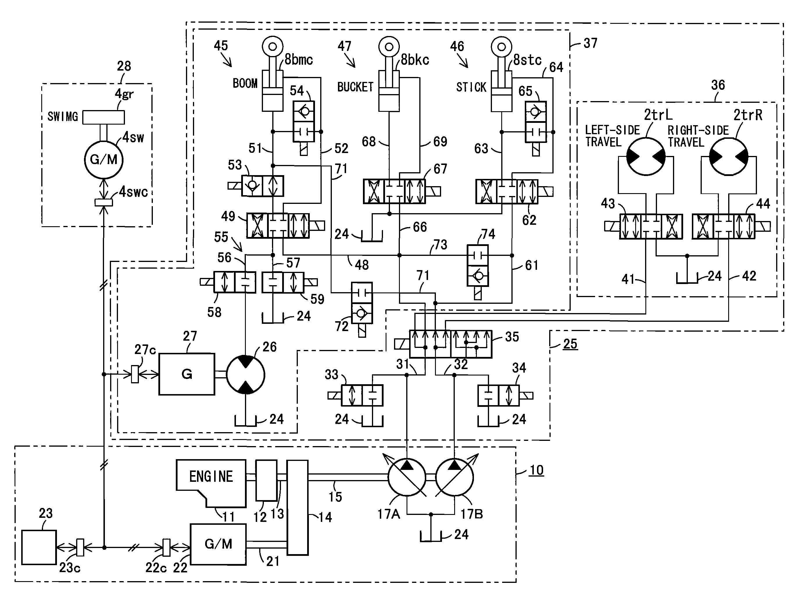
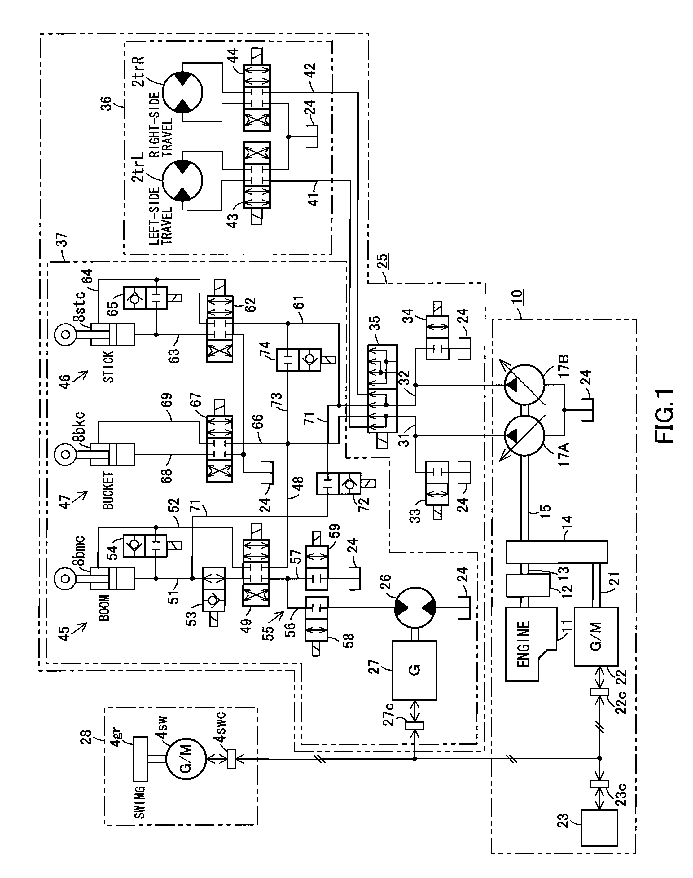
[0034]Next, the present invention is explained in detail hereunder, referring to an embodiment thereof shown in FIGS. 1 and 2, another embodiment shown in FIG. 3, a further embodiment shown in FIG. 4, an embodiment shown in FIG. 5, another embodiment shown in FIG. 6, a further embodiment shown in FIG. 7, and a variant of a hybrid drive system shown in FIG. 8.

[0035]The embodiment shown in FIGS. 1 and 2 is explained.

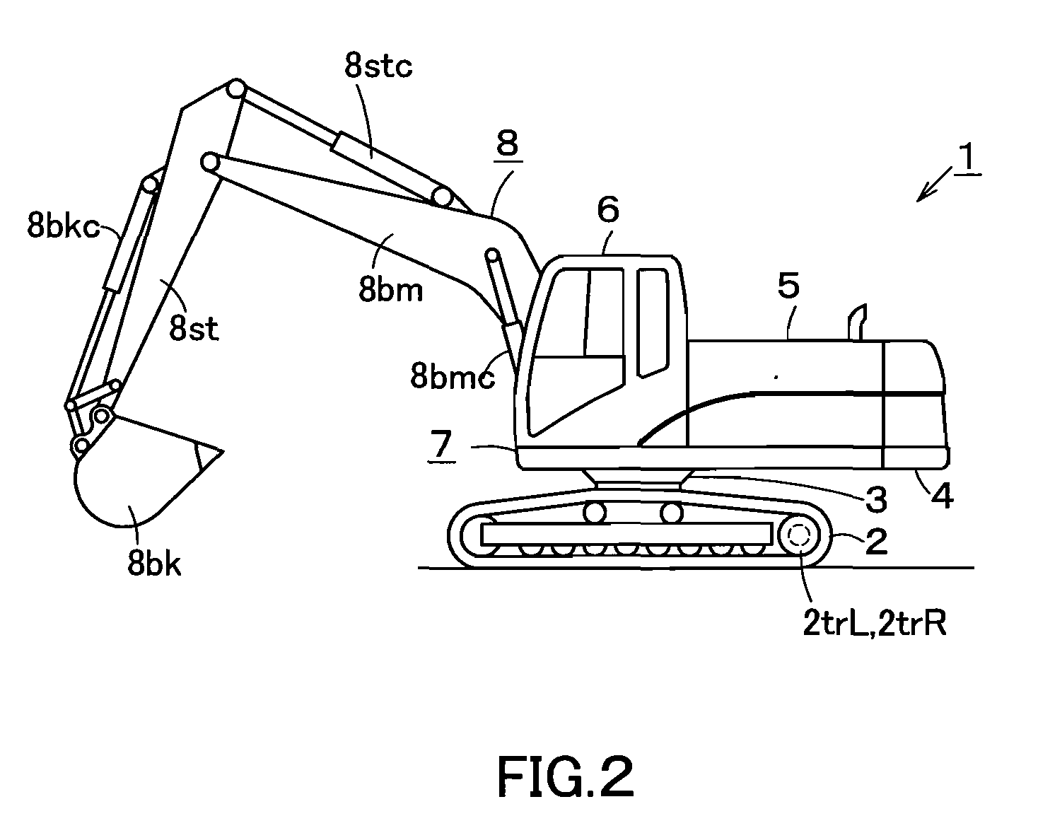
[0036]As shown in FIG. 2, a work machine 1 is a hydraulic excavator that includes a machine body 7. The machine body 7 is comprised of a lower structure 2, an upper structure 4 rotatably mounted on the lower structure 2 with a swing bearing portion 3 therebetween, and components mounted on the upper structure 4. The components mounted on the upper structure 4 include a power unit 5 comprised of an engine, hydraulic pumps, etc., and a cab 6 for protecting an operator. The lower structure 2 is provided with travel motors 2trL,2trR for respectively driving right and left craw...


PUM


Abstract

A hydraulic circuit that enables smooth absorption of the energy of a return fluid from a hydraulic actuator by means of an energy recovery motor. A return fluid passage to which the fluid discharged from a boom cylinder is branched is provided at the tank passage side of a solenoid valve of a boom control circuit. The return fluid passage comprises two return passages, which are provided with a flow rate ratio control valve for controlling a ratio of fluid that branches off into the return passages. The flow rate ratio control valve is comprised of a solenoid valve disposed in the return passage, which is provided with an energy recovery motor, and a solenoid valve disposed in the return passage, which branches off the upstream side of the solenoid valve.

Description

CROSS REFERENCE TO RELATED APPLICATIONS[0001]This is a U.S. national phase application under 35 U.S.C. § 371 of International Patent Application No. PCT / JP2006 / 303564, filed Feb. 27, 2006 and claims the benefit of Japanese Application No. 2005-166177, filed Jun. 6, 2005; Japanese Application No. 2005-166178, filed Jun. 6, 2005; Japanese Application No. 2005-166179, filed Jun. 6, 2005 and Japanese Application No. 2005-166180, filed Jun. 6, 2005. The International Application was published in Japanese on Dec. 14, 2006 as International Publication No. WO 2006 / 132010 under PCT Article 21(2). The contents of all the above applications are incorporated herein in their entirety.TECHNICAL FIELD[0002]The present invention relates to a hydraulic circuit provided with an energy recovery motor; an energy recovery device; and a hydraulic circuit for a work machine provided with a boom assist.BACKGROUND OF THE INVENTION[0003]A driving system for a work machine, such as a hydraulic excavator, typi...

Claims


Application Information

Patent Timeline
IPC IPC(8): F15B21/14F15B13/044H02K7/18
CPCE02F9/2075F15B2211/88E02F9/2225E02F9/2239E02F9/2246E02F9/2292E02F9/2296F15B11/024F15B11/17F15B21/14F15B2211/20515F15B2211/20523F15B2211/20546F15B2211/20576F15B2211/265F15B2211/7053F15B2211/7058E02F9/2217
Inventor TOZAWA, SHOJIBINNAKA, MADOKAFURUTA, HIDETO
Owner CATEPILLAR SARL
Why Eureka
Try Eureka