Omni-directional, multi-polarity, low profile planar antenna

a planar antenna, omni-directional technology, applied in the direction of resonant antennas, antenna earthings, differential interacting antenna combinations, etc., can solve the problems of inability to adjust the length and direction of the dipole elements, the performance of such conventional indoor vhf/uhf antennas changes in response, and the physical dimension of the vhf dipole is undetected, so as to optimize the reception of atsc television broadcast signals. , excellen

Active Publication Date: 2009-11-26
VOXX INT CORP
View PDF4 Cites 7 Cited by
  • Summary
  • Abstract
  • Description
  • Claims
  • Application Information

AI Technical Summary

Benefits of technology

[0015]It is still a further object of the present invention to provide a television antenna which resolves issues with multi-path and other forms of interference from adjacent channels, as well as maintain an excellent SWR (standing wave ratio) with proper impedance matching between the ATSC tuner on the television side and the output impedance of the antenna.
[0016]It is still another object of the present invention to provide a television antenna which optimizes ATSC television broadcast signal reception, as well as resolve the channel drop off problem when the antenna is not pointed to the right direction with the right polarization.

Problems solved by technology

One problem associated with the conventional indoor antenna systems is that the physical dimension of the VHF dipole is undesirably long for the ordinary setting in a living room and that the length as well as the direction of the dipole elements may need to be adjusted depending upon the receiving channels.
The second problem is that the performance of such conventional indoor VHF / UHF antennas changes in response to changes of the physical conditions around the antenna elements.
For example, it is difficult for a user to make proper adjustment of the antennas since a human body coming into contact with an antenna changes the electro-magnetic conditions associated with the antenna elements.
The third problem is that the conventional indoor antenna systems do not always provide a sufficient signal level for good reception.
Without a good omni-directional TV antenna, consumers will not be able to receive all of the digital ATSC signals when the broadcast format change comes about.

Method used


Image

  • Omni-directional, multi-polarity, low profile planar antenna
  • Omni-directional, multi-polarity, low profile planar antenna
  • Omni-directional, multi-polarity, low profile planar antenna

Examples


Embodiment Construction

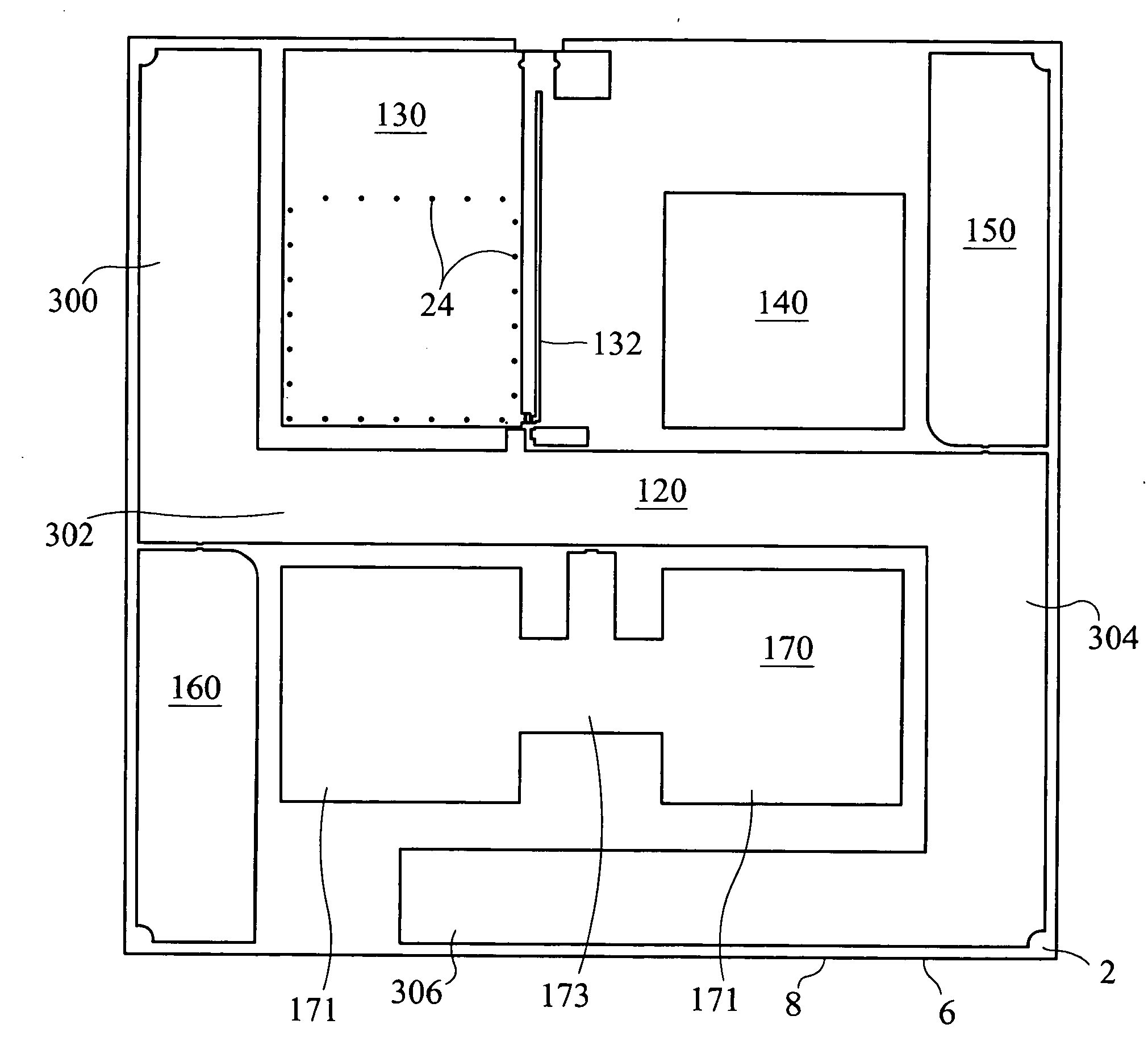
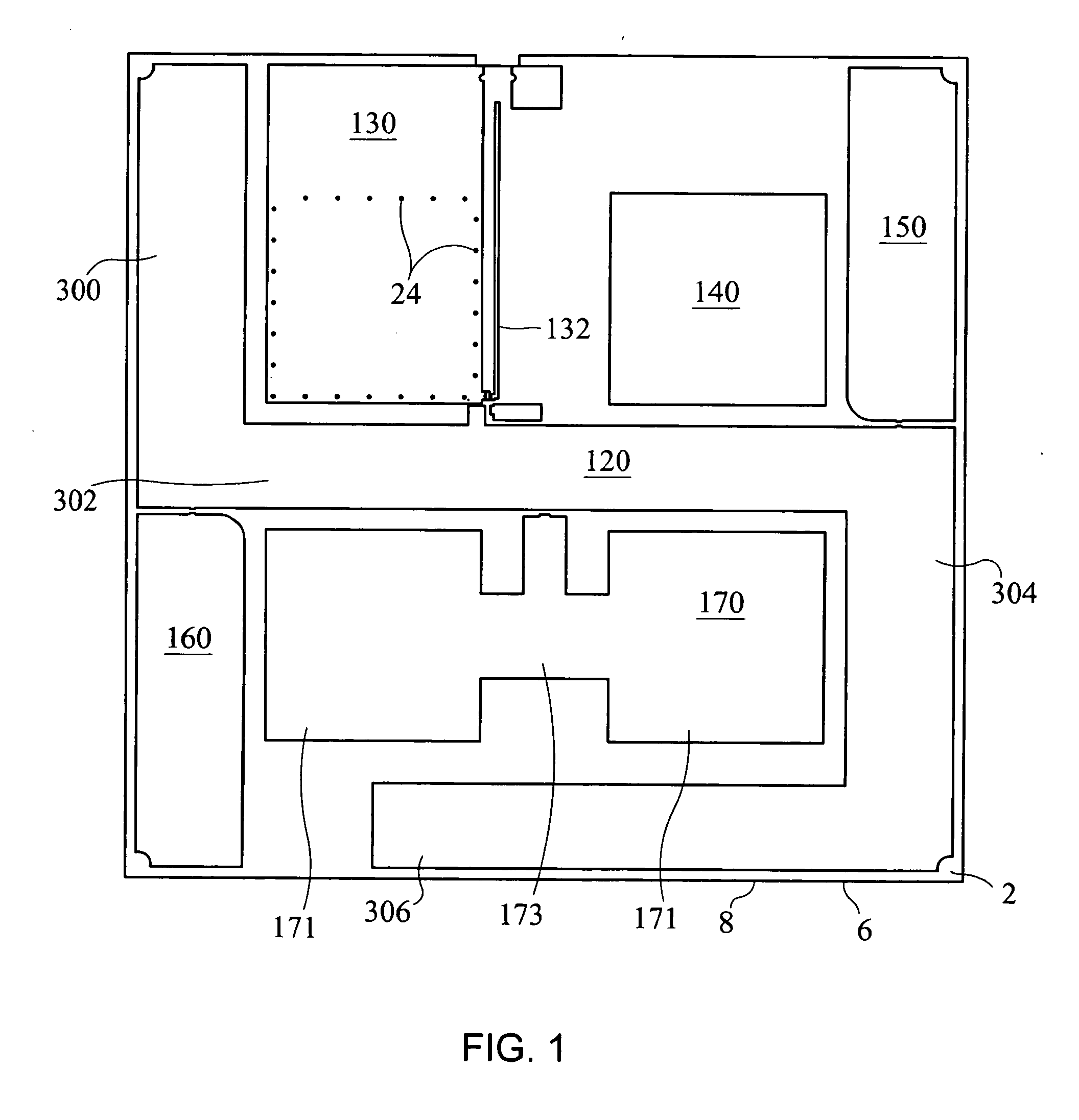
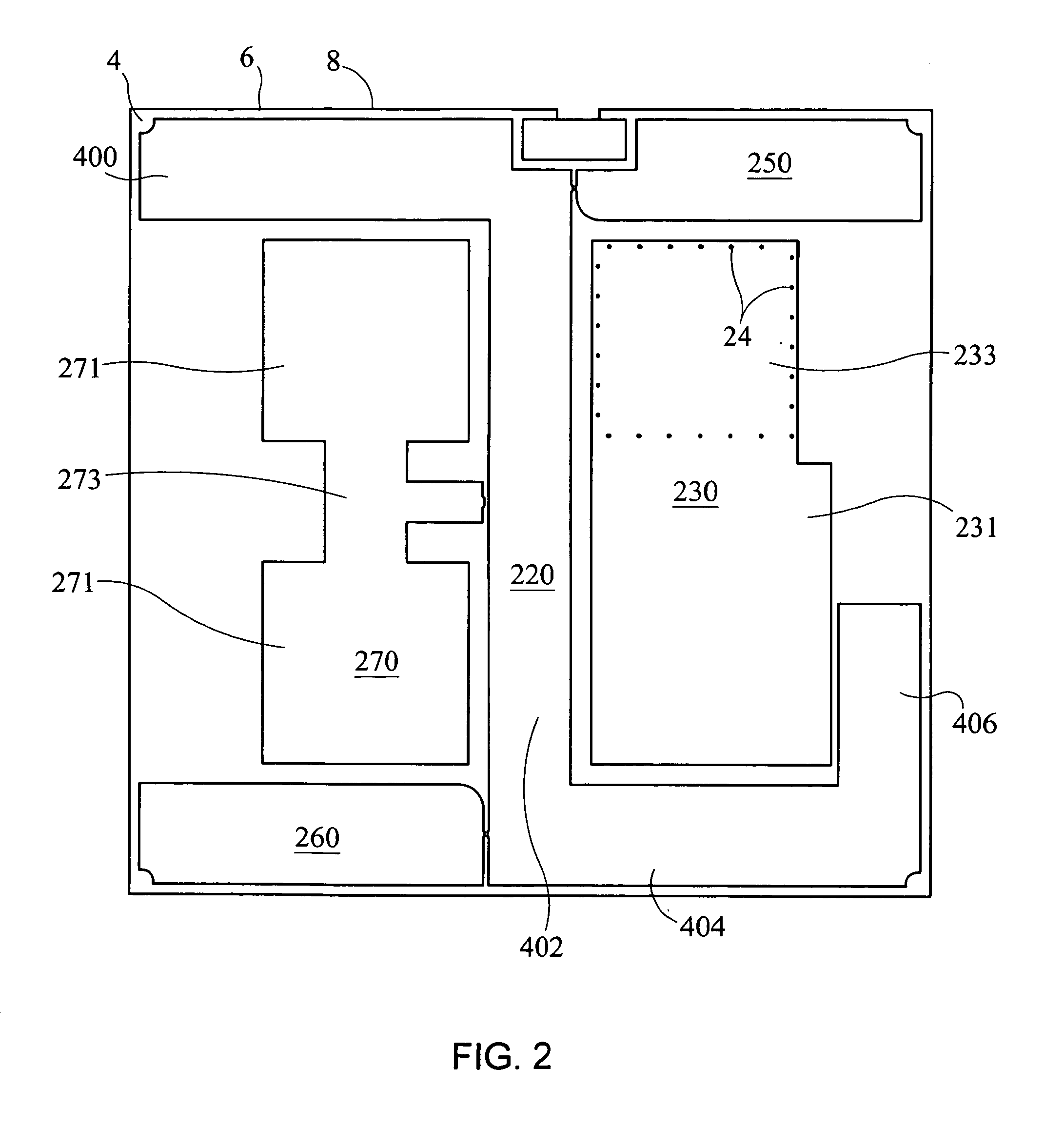
[0029]Referring initially to FIGS. 1-4 of the drawings, it will be seen that an omni-directional, multi-polarity, low profile planar antenna constructed in accordance with a first form of the present invention includes elements which are developed based on microstrip techniques and which are situated on a first side 2 and an opposite second side 4 of a planar substrate 6 having dielectric properties. More specifically, the antenna elements on both sides of the substrate 6 are dimensioned and arranged in unique patterns which make it possible for the planar antenna to provide omni-directional reception of horizontally polarized and vertically polarized television signals, the omni-directionality properties of the antenna being seen from the radiation pattern plot of the antenna shown in FIG. 5. Thus, no adjustment for the direction of the antenna is necessary once it is installed by the user. The omni-directionality of the planar antenna of the present invention is believed to result...


PUM


Abstract

An omni-directional, multi-polarity, low profile planar antenna for receiving high definition television signals includes a dielectric substrate having a first side and a second side on which are respectively formed first and second conductive patterns. Each conductive pattern includes segments functioning as antenna elements which are arranged to form a first modified H-shaped pattern on the first side of the dielectric substrate, and a second modified H-shaped pattern on the second side of the dielectric substrate which is disposed substantially ninety degrees with respect to the first modified H-shaped pattern. Each of the H-shaped patterns includes an extended S-shaped segment.

Description

CROSS-REFERENCE TO RELATED APPLICATION[0001]This application is related to U.S. Provisional Application Ser. No. 61 / 128,801, filed on May 23, 2008, and entitled “Omni-Directional, Multi-Polarity, Low Profile Planar Antenna”, the disclosure of which is incorporated herein by reference. This application claims the benefit of priority under 35 U.S.C. 119 and / or 35 U.S.C. 120 to the aforementioned related provisional application.BACKGROUND OF THE INVENTION[0002]1. Field of the Invention[0003]The present invention generally relates to antennas for receiving broadcast signals such as television signals, and more specifically relates to television antennas for receiving digitally formatted broadcast signals.[0004]2. Description of the Prior Art[0005]Conventional indoor TV antenna systems generally include two separate antennas for respective VHF and UHF reception. The antenna for receiving the VHF bands employs a pair of telescopic elements forming a dipole with each of the elements having...

Claims


Application Information

Patent Timeline
Patent Type & Authority Applications(United States)
IPC IPC(8): H01Q1/38
CPCH01Q21/29H01Q1/38
Inventor TINAPHONG, PRAPAN PAULYIN, HONG
Owner VOXX INT CORP
Why Eureka
Try Eureka