
Multilayer ceramic capacitor and method for manufacturing the same

a multi-layer ceramic capacitor and ceramic technology, applied in the direction of fixed capacitors, variable capacitors, fixed capacitor details, etc., can solve the problems of inability to suppress, increase the resistance of the lower layer resistance electrode or the resistance of the interface portion in some cases, disadvantageous increase of the impedance, etc., to achieve stable aimed esr value, increase the resistance, and improve the reliability of the multi-layer ceramic capacitor

Active Publication Date: 2009-11-26
MURATA MFG CO LTD
View PDF6 Cites 17 Cited by
  • Summary
  • Abstract
  • Description
  • Claims
  • Application Information

AI Technical Summary

Benefits of technology

[0012]Accordingly, an object of the present invention is to provide a multilayer ceramic capacitor which can solve the problem described above and a method for manufacturing the above multilayer ceramic capacitor.
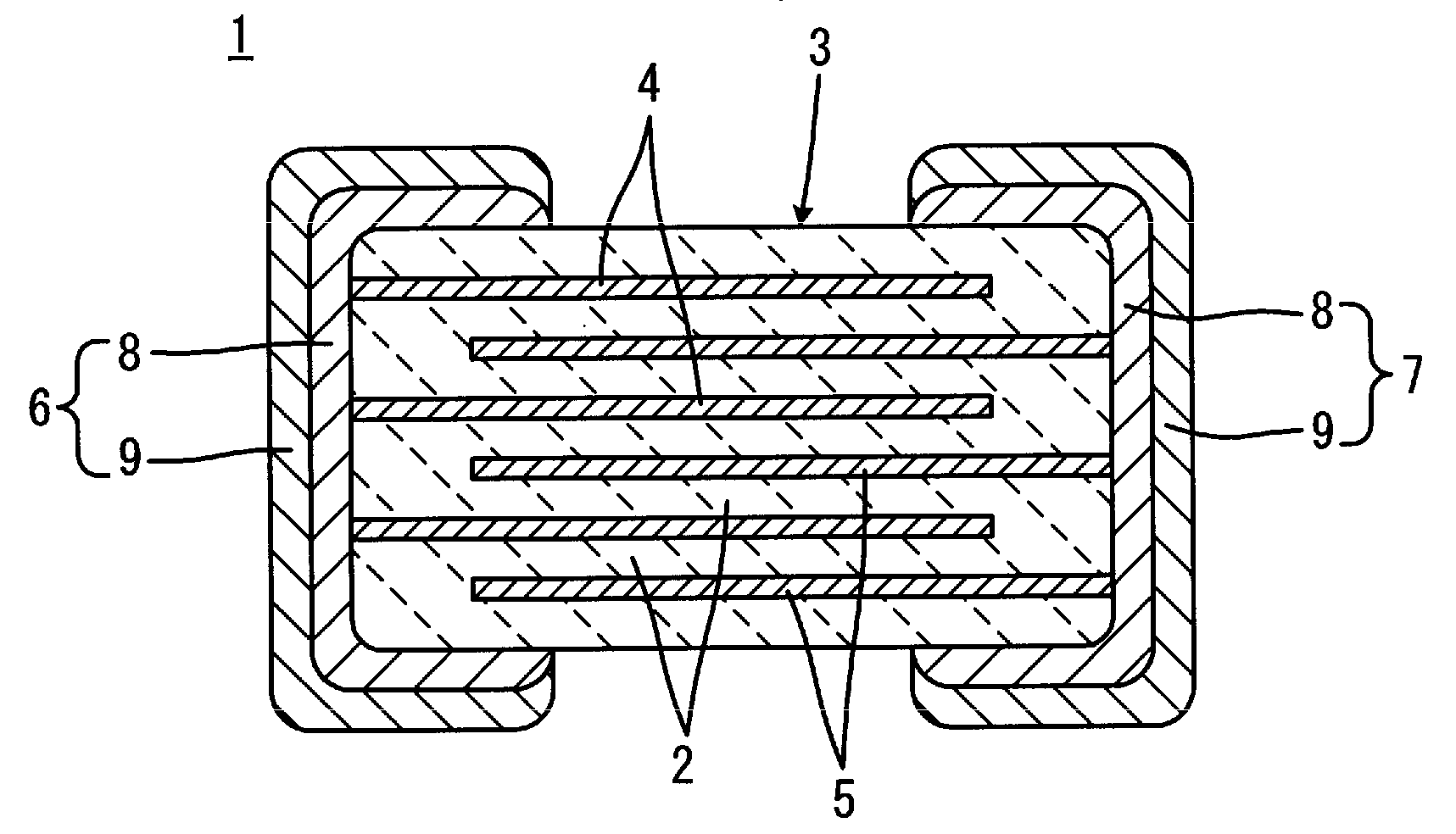
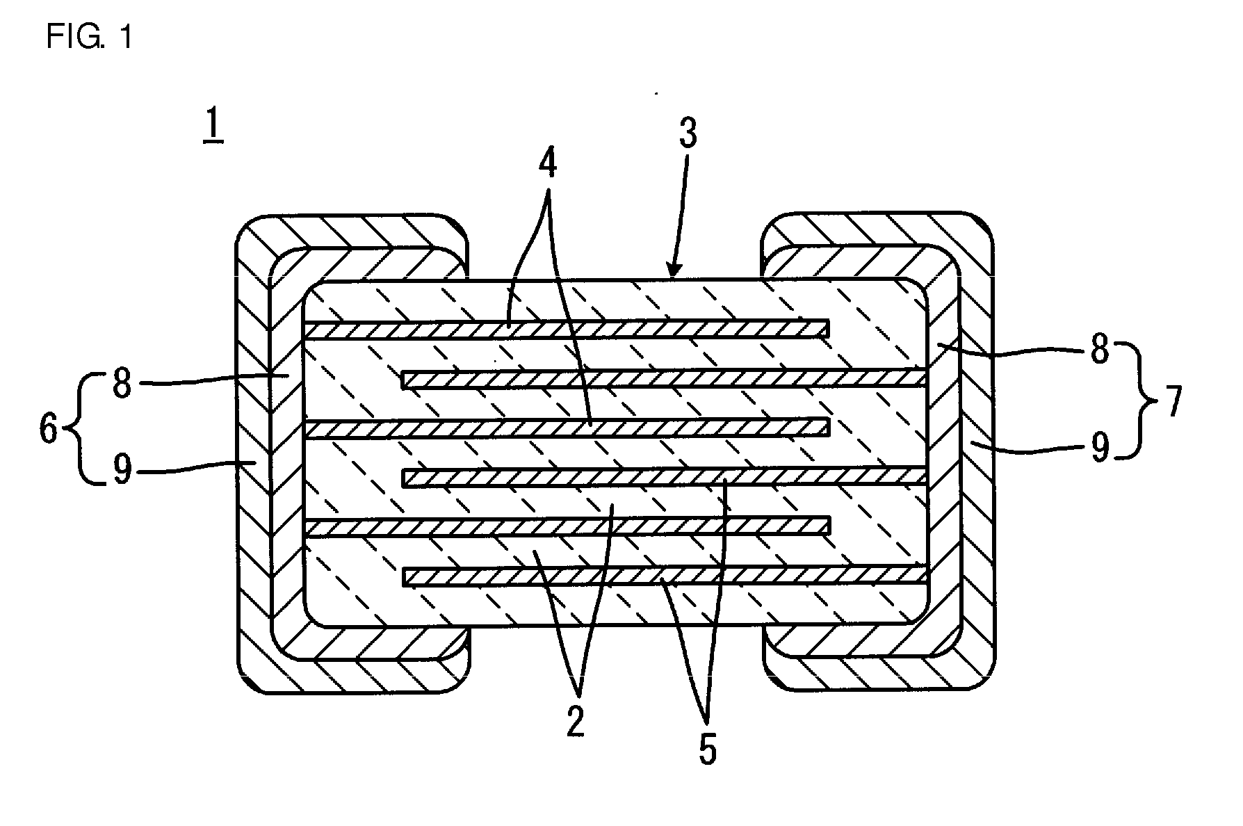
[0019]According to the present invention, since a glass having a softening point higher than that of the lower layer resistance electrode by 20° C. or more is used in the upper layer conductive electrode, in firing to form the upper layer conductive electrode, the flow of glass into the lower layer resistance electrode and toward an interface portion between the upper layer conductive electrode and the lower layer resistance electrode can be suppressed. As a result, an increase in resistance at the lower layer resistance electrode and that at the interface portion between the lower layer resistance electrode and the upper layer conductive electrode can be suppressed, and hence a stable aimed ESR value can be obtained.
[0020]In addition, since the softening point of the glass used in the upper layer conductive electrode is set higher, sealing properties of the upper layer conductive electrode against a plating liquid are improved, and the reliability of the multilayer ceramic capacitor can be improved. Furthermore, solder explosion (phenomenon in which as a plating liquid entering the electrode is gasified in soldering, a solder ball is splashed) can be made unlikely to occur. In particular, when the ratio of a glass network forming element, such as SiO2, is increased in order to increase the softening point of the glass, the above sealing properties against a plating liquid can be further improved.
[0021]In the multilayer ceramic capacitor of the present invention, when the glass contained in the upper layer conductive electrode is a glass which is to be crystallized in a firing step of forming the upper layer conductive electrode, since the viscosity of the glass increases, and the flow thereof toward the lower layer resistance electrode side can be further suppressed, the aimed ESR value can be further stabilized.
[0022]According to the method for manufacturing a multilayer ceramic capacitor of the present invention, since the firing temperature for forming the upper layer conductive electrodes is lower than that for forming the lower layer resistance electrodes, a problem of bond break between the lower layer resistance electrode and the upper layer conductive electrode can be avoided.
[0023]In the method for manufacturing a multilayer ceramic capacitor of the present invention, when the firing temperature for forming the upper layer conductive electrodes is lower than that for forming the lower layer resistance electrodes by 10° C. or more, and when the softening point of the second glass contained in the upper layer conductive electrode is lower than the firing temperature for forming the upper layer conductive electrodes by 50° C. or more, the bond break between the lower layer resistance electrode and the upper layer conductive electrode can be more reliably avoided, and the upper layer conductive electrodes can be sufficiently sintered.

Problems solved by technology

When a multilayer ceramic capacitor is used in the vicinity of a CPU for a decoupling application, since an equivalent series resistance (ESR) of the multilayer ceramic capacitor is excessively low, oscillation is generated on a circuit due to parallel resonance, and as a result, the impedance disadvantageously increases.
However, for example, when the same glass as that in the lower layer resistance electrode is used in the upper layer conductive electrode, in the firing to form the upper layer conductive electrode, the flow of glass from the upper layer conductive electrode into the lower layer resistance electrode or toward the interface portion therebetween cannot be suppressed, and as a result, the resistance of the lower layer resistance electrode or the resistance of the interface portion may increase in some cases.
As a result, the ESR may exceed an ESR value aimed only by the lower layer resistance electrode in some cases, and the control (adjustment) of the aimed ESR value is difficult to perform.

Method used


Image

  • Multilayer ceramic capacitor and method for manufacturing the same
  • Multilayer ceramic capacitor and method for manufacturing the same
  • Multilayer ceramic capacitor and method for manufacturing the same

Examples


experimental example 1

[0066]First, by a known method, a ceramic laminate for a multilayer ceramic capacitor was prepared which was designed to contain Ni in internal electrodes and to obtain an electrostatic capacitance of 1 μF.

[0067]In addition, a paste for lower layer resistance electrodes was prepared as described below.

[0068]After an In2O3 powder and a SnO2 powder were mixed together so that the content of the SnO2 powder to the total amount of the In2O3 powder and the SnO2 powder was 5 percent by weight and were then calcined in the air at a temperature of 1,400° C. for 5 hours so that SnO2 was sufficiently solid-solved, a pulverizing treatment was performed until a powder having an average particle diameter of approximately 1 μm was obtained, so that an In—Sn composite oxide powder was obtained.

[0069]In addition, as a first glass, a glass frit composed of a B—Si—Zn—Ba—Ca-based glass, having a softening point shown in “First Glass Softening Point” in Table 1, and having an average particle diameter ...

experimental example 2

[0085]In Experimental Example 2, after multilayer ceramic capacitors of Samples 13 and 14 were formed as shown in Table 2 under conditions similar to those of Samples 4 and 10, respectively, of Experimental Example 1 except that as the second glass contained in the upper layer conductive electrode, a glass was used which was crystallized in a firing step of forming the upper layer conductive electrodes, evaluation similar to that in Experimental Example 1 was performed. The evaluation results are shown in Table 2. In addition, in Table 2, the crystallization start temperature of the second glass of each of Samples 13 and 14 are also shown.

TABLE 2Firing Temperature ofSofteningCrystallization StartFiring Temperature ofSampleSoftening PointLower LayerPoint ofTemperature ofUpper LayerESRRate of ChangeNo.of First GlassResistance ElectrodeSecond GlassSecond GlassConductive ElectrodeValuein ESR4560° C.720° C.580° C.—670° C.155 mΩ+3%13560° C.720° C.580° C.650° C.670° C.151 mΩ+0%10620° C.780...


PUM

PropertyMeasurementUnit
Temperatureaaaaaaaaaa

Abstract

A multilayer ceramic capacitor having external electrodes. Each of the external electrodes has a lower layer resistance electrode and an upper layer conductive electrode. A glass contained in the upper layer conductive electrode has a softening point higher than that of a glass contained in the lower layer resistance electrode by 20° C. or more.

Description

CROSS REFERENCE TO RELATED APPLICATIONS[0001]The present application is a continuation of International Application No. PCT / JP2008 / 052105, filed Feb. 14, 2008, which claims priority to Japanese Patent Application No. JP2007-033151, filed Feb. 14, 2007, the entire contents of each of these applications being incorporated herein by reference in their entirety.FIELD OF THE INVENTION[0002]The present invention relates to a multilayer ceramic capacitor and a method for manufacturing the same, and more particularly relates to a multilayer ceramic capacitor which includes external electrodes each also functioning as a resistance element so as to be used as a CR composite electronic device and to a method for manufacturing the above multilayer ceramic capacitor.BACKGROUND OF THE INVENTION[0003]When a multilayer ceramic capacitor is used in the vicinity of a CPU for a decoupling application, since an equivalent series resistance (ESR) of the multilayer ceramic capacitor is excessively low, o...

Claims


Application Information

Patent Timeline
IPC IPC(8): H01G4/008H01G4/005
CPCH01G4/2325Y10T29/435H01G4/30
Inventor NAGAMOTO, TOSHIKIKUSANO, MITSUHIRO
Owner MURATA MFG CO LTD
Learn More