Connection structure

a technology of connecting structure and connecting element, applied in the direction of connecting the coupling device, contact member penetrating/cutting the insulation/cable strand, lighting support device, etc., can solve the problems of high investment and high quality control requirements of facilities, and achieve the effect of easy connection of led components

Inactive Publication Date: 2009-11-26
TOYOTA BOSHOKU KK +2
View PDF3 Cites 9 Cited by
  • Summary
  • Abstract
  • Description
  • Claims
  • Application Information

AI Technical Summary

Benefits of technology

[0007]The present invention has an object of providing a connection structure capable of easily connecting an LED component to a flat cable.
[0017]The present invention provides a connection structure capable of easily connecting an LED component to a flat cable.

Problems solved by technology

This involves a problem that for connecting an LED component, which is more and more decreasing in size such as an LED chip having a planar size of, for example, 2 mm×2 mm, a great amount of facility investment and highly precise quality control are required.

Method used


Image

  • Connection structure
  • Connection structure
  • Connection structure

Examples


Embodiment Construction

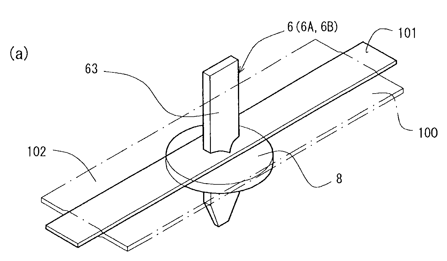
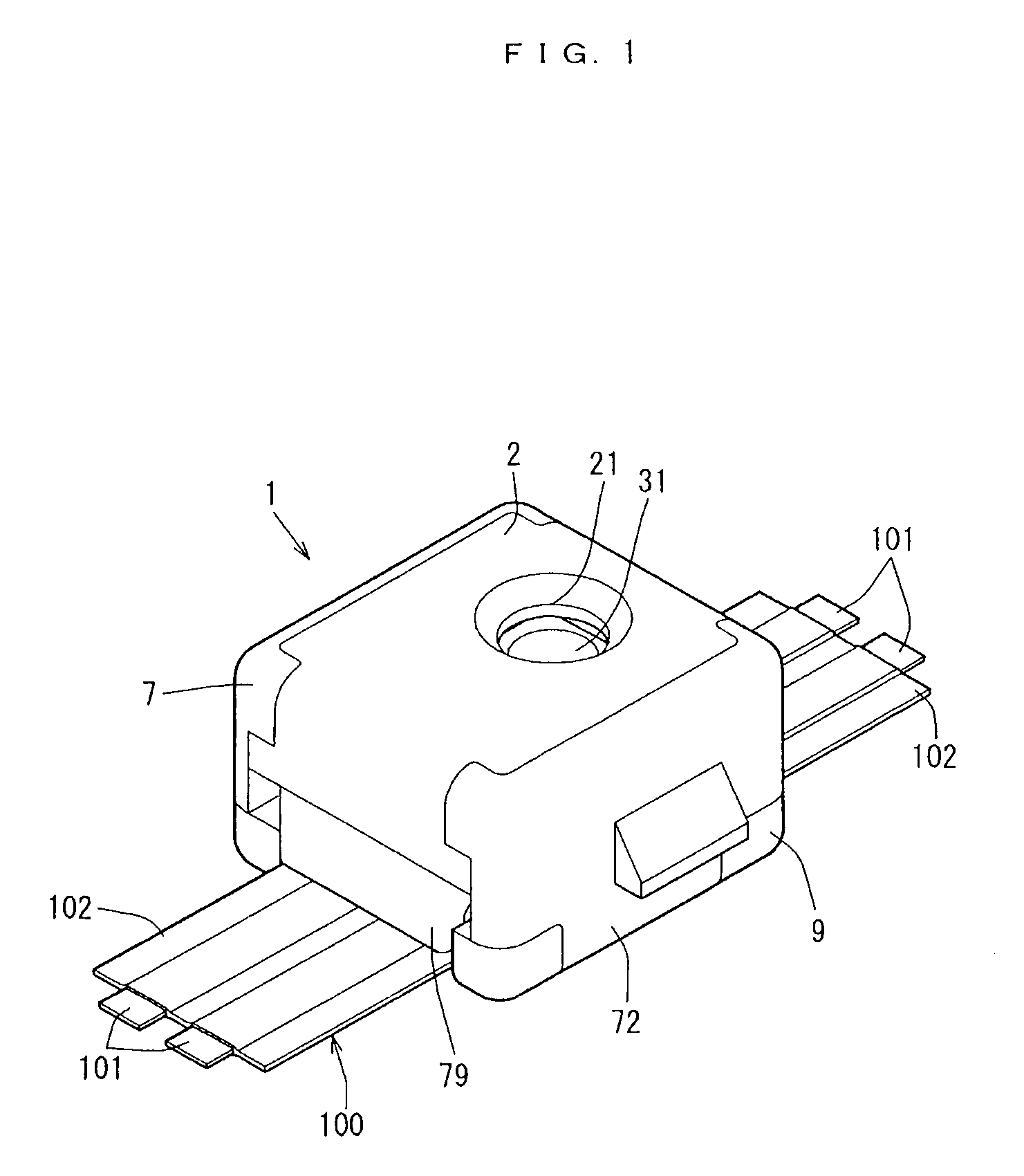
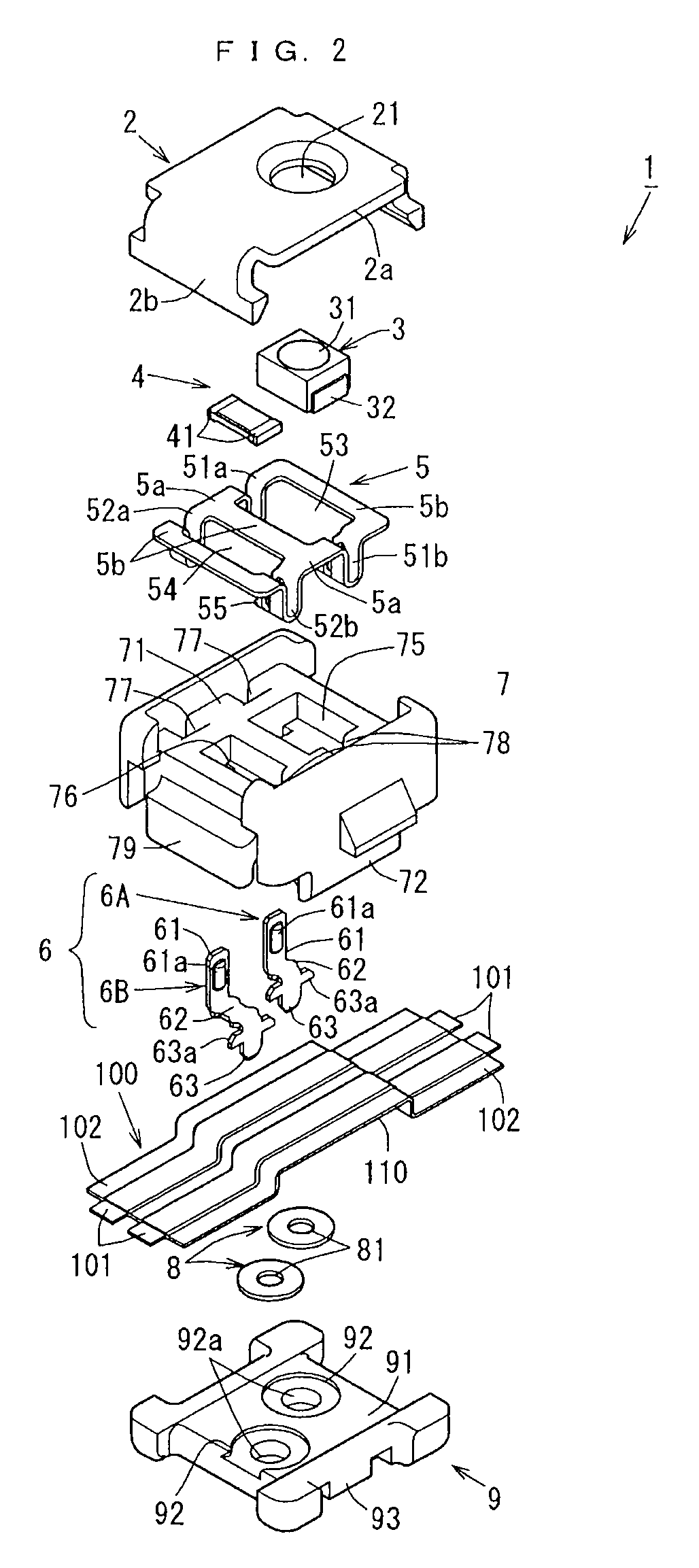
[0045]An LED unit according to the present invention includes an upper case 7 for holding an LED chip 3, a pierce terminal 6A for LED for electrically connecting the LED chip 3 to a flat cable 100, and a lower case 9 located oppositely to the upper case 7 with respect to the flat cable 100 and fit with the upper case 7 for holding and attaching the flat cable 100 between the lower case 7 and the upper case 7.

[0046]The LED unit 1 further includes an intermediate terminal 5 for causing the upper case 7 to hold the LED chip 3 and connecting the LED chip 3 to the pierce terminal 6A.

[0047]The intermediate terminal 5 includes a pair of convexed springs 51. Among the convexed springs 51 (51a, 51b), one convexed spring 51a is engaged with the upper case 7, and the other convexed spring 51b presses the LED chip 3 to the pierce terminal 6A.

[0048]The LED chip 3 and the pierce terminal 6A to which the LED chip 3 is pressed are located between the pair of convexed springs 51a and 51b.

[0049]The ...


PUM


Abstract

The present invention has an object of providing a connection structure capable of easily connecting an LED component to a flat cable. An LED unit 1 includes an upper case 7, a pierce terminal 6, a lower case 9 and an intermediate terminal 5. An LED chip 3 is pressed to the pierce terminal 6 by a convexed spring 51 to electrically connect the LED chip 3 to the flat cable 100. Conductors 101 included in the flat cable 100 are formed of phosphor bronze formed of tin (Sn), phosphorus (P), copper (Cu) and unavoidable impurities and having a tensile strength of 480 to 550 MPa, whereas a pierce plate 63 of the pierce terminal 6 piercing through the conductor 101 is formed of a copper alloy, which is a high strength conductive member having a higher strength than that of the conductor 101 and having conductivity.

Description

BACKGROUND OF THE INVENTION[0001]1. Field of the Invention[0002]The present invention relates to a connection structure for connecting an LED component usable for, for example, an illumination device or the like of a vehicle to a flat cable.[0003]2. Description of the Prior Art[0004]Conventionally, an electronic component-mounted module including a plurality of electronic components mounted on a printed board is used for various types of control units, illumination devices, or the like of automobiles. For example, such an electronic component-mounted module includes the electronic components mounted on the board by solder connection, and the electronic component-mounted module is connected to an external electric circuit by a connector having a terminal connected to the board by soldering (see Patent Document 1).[0005]The electronic components and the circuit conductor are connected to each other by soldering. This involves a problem that for connecting an LED component, which is mo...

Claims


Application Information

Patent Timeline
Patent Type & Authority Applications(United States)
IPC IPC(8): H01R4/24H01L33/48H01L33/62
CPCF21V21/002F21Y2101/02H01R12/675H01R33/94F21Y2115/10
Inventor SATO, MASANOBUSHIBATA, KENICHISANO, YOSHISADAENOMOTO, NORITSUGUYABU, TAKENOBUKUBOKI, NAOBUMIMOTOMURA, SHIGEKIIKEDA, TAKEHIDE
Owner TOYOTA BOSHOKU KK
Why Eureka
Try Eureka