Method for recovery of lost and/or corrupted data

a data recovery and corrupted technology, applied in the field of recovery of lost and/or corrupted data, can solve the problems of large complexity, high data rate can often not be reached, incorrectly received or considered lost packets, etc., to improve the quality of recovery rate, improve service quality, and increase the abortion parameter

Active Publication Date: 2009-11-26
DEUTSCHES ZENTRUM FUER LUFT & RAUMFAHRT EV
View PDF6 Cites 27 Cited by
  • Summary
  • Abstract
  • Description
  • Claims
  • Application Information

AI Technical Summary

Benefits of technology

[0044]The amount of the abortion parameter can be selected by the user of the receiver device on the basis of the available computing power of the receiver device, the current operational burden imposed on a processor of the receiver device, the desired quality of service and/or the available capacity of an energy store of the receiver device. Thus, for instance, it is possible to improve the quality of the recovery rate by increasing the abortion parameter. Thereby, the quality of

Problems solved by technology

On the levels above the physical layer, packets are either correctly received or are considered lost in that they are erased because the CRC has detected a corrupted packet in the physical layer.
With increased block lengths, decoders of this type which are based on Gaussian elimination will be of a massively increased complexity so that high data rates can often not be reached.
This imposes an upper limit on the ability to recover lost and/or corrupted data.
A reduction of the complexity of the maximum-likelihood decoder does lead to an improved performance but is

Method used


Image

  • Method for recovery of lost and/or corrupted data
  • Method for recovery of lost and/or corrupted data
  • Method for recovery of lost and/or corrupted data

Examples


Embodiment Construction

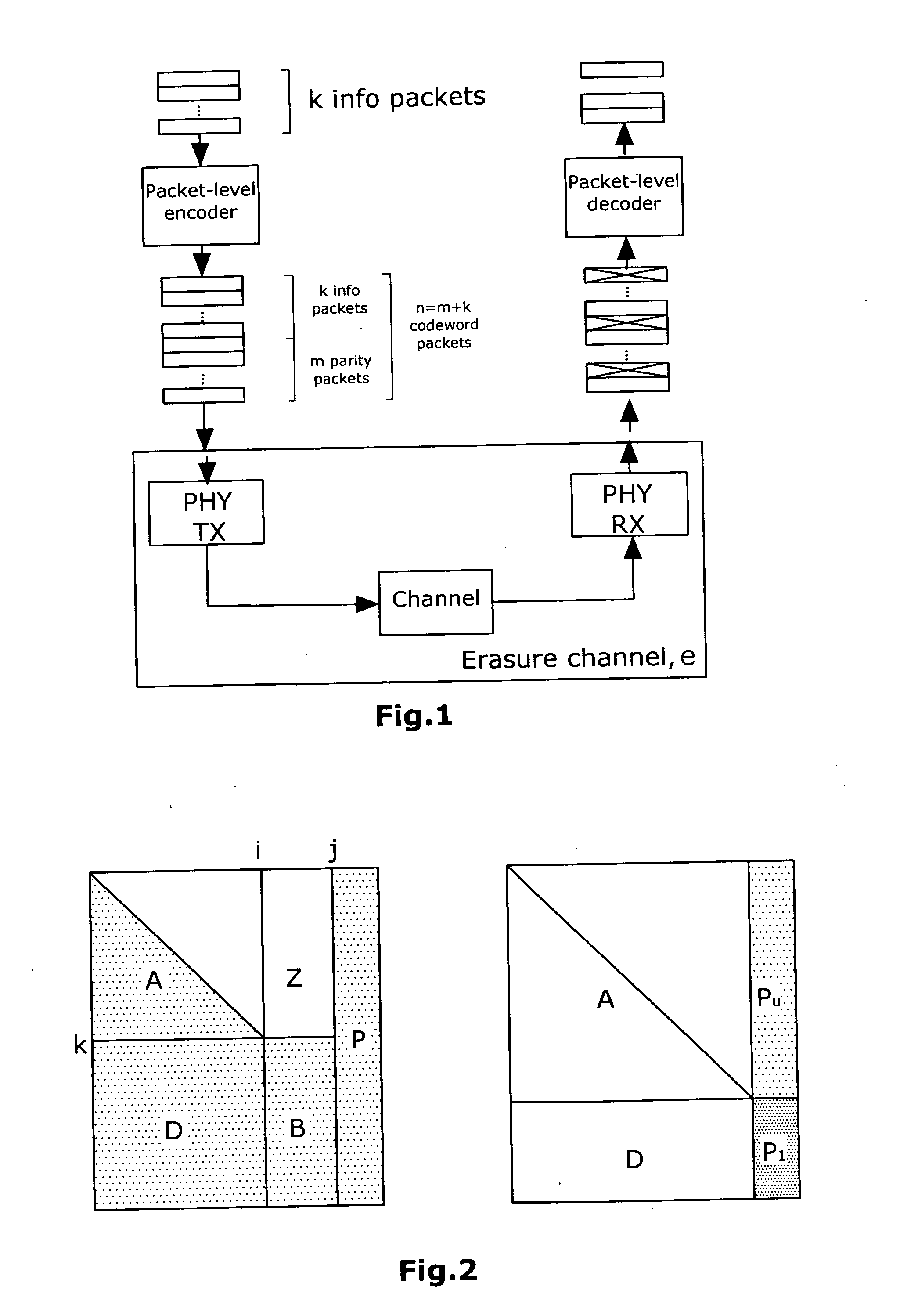
[0061]From FIG. 2, as already described, it is evident in which manner the sub-matrix A has to be enlarged by shifting columns of the sub-matrix B into the sub-matrix P. The right-hand side of FIG. 2 represents the matrix H after the sub-matrix D has been zeroed out so that the Gaussian elimination method has to be applied only to the sub-matrix P1.

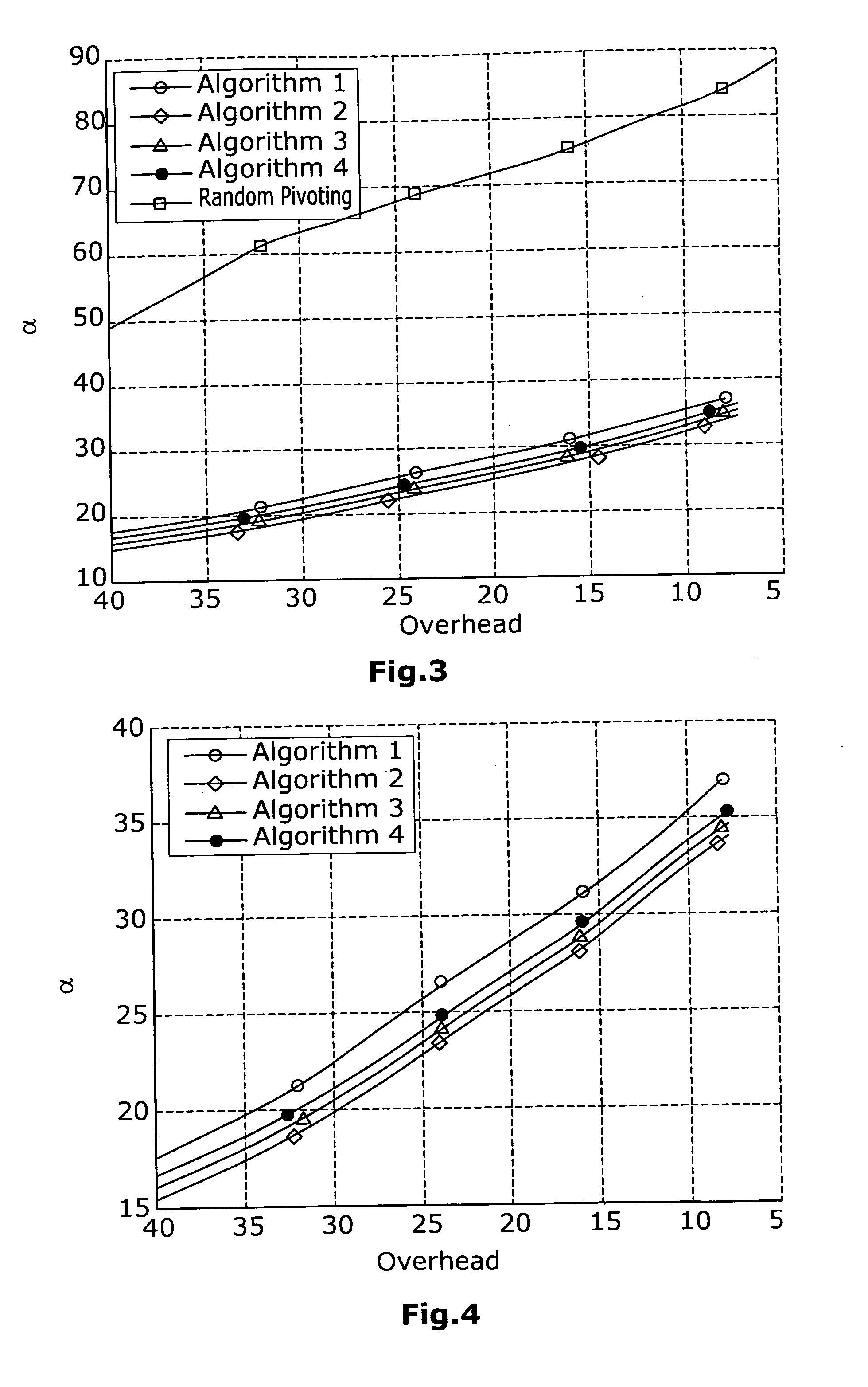
[0062]FIGS. 3 and 4 show the pivoting value α, namely the block length of the sub-matrix P, i.e. the number of columns which have been displaced, in dependence on the overhead. The overhead herein is dependent on the channel erasure rate. The average pivot size a was simulated for various overheads in one hundred different tests. Herein, there was used an Irregular Repeat Accumulate (IRA) (2048, 1024) Code. In the best case, such a code can tolerate 1024 erasures. Thus, the overhead can be expressed as: Overhead=1024−actual number of erasures in the codeword.

[0063]The simulation results for the first four inventive algorithms are visualiz...


PUM


Abstract

A method for recovery of lost and/or corrupted data transmitted from a transmitter device to a receiver device. The data is coded by an encoder connected to the transmitter device. The data is transmitted from the transmitter device to the receiver device via a transmission system and is decoded by means of a decoder connected to the receiver device. This is performed through application of a low density parity check method, wherein lost and/or corrupted data is restored during decoding. The decoding is performed by solving the equation system of the parity check matrix H. The parity check matrix H is brought into a triangular form by column and/or row permutations. Columns of a sub-matrix B of the matrix H which impede the triangulation process are shifted into a sub-matrix P of the matrix H so that the triangulation process can be continued until the matrix H except for the sub-matrix P has been completely brought into a triangular form. The Gaussian elimination method is applied to a part of the sub-matrix P. The selection of the column or columns of the sub-matrix B which are to be shifted into the sub-matrix P is performed on the basis of the weight of the column which corresponds to the number of non-zero-entries in the column, and/or on the basis of the weight of the rows of the sub-matrix B connected to the column.

Description

BACKGROUND[0001]1. Field of the Disclosure[0002]The present invention relates to a method for recovery of lost and / or corrupted data which is transmitted from a transmitter device to a receiver device.[0003]2. Discussion of the Background Art[0004]The transmitted data can be audio or video streams, for instance. From a transmitter device which makes these data available, the data is transmitted e.g. to a mobile receiver device. The mobile receiver device can be, for instance, a mobile phone, a PDA or another mobile end device. Alternatively, data can also be transmitted from a transmitter device to a stationary receiver device.[0005]Examples of standards used for the transmission of data to mobile end devices include DVB-H, MBMS and, to be expected in the near future, DVB-SH.[0006]In order to guarantee a good transmission quality, it is required to verify the correct transmission of data or data packets to the receiver device. Various methods exist for recovery of lost and / or corrup...

Claims


Application Information

Patent Timeline
IPC IPC(8): H03M13/05G06F11/10
CPCH04L1/005H04L1/0057H04L1/0054
Inventor LIVA, GIANLUIGIMATUZ, BALAZS
Owner DEUTSCHES ZENTRUM FUER LUFT & RAUMFAHRT EV
Why Eureka
Try Eureka