
Memory device and method of storing data

a memory device and data technology, applied in the field of memory devices and methods of storing data, can solve the problems of increased read-failure rate, reduced threshold voltage between adjacent bits, and data error reduction, so as to improve the reliability of memory devices and reduce data errors

Inactive Publication Date: 2009-11-26
SAMSUNG ELECTRONICS CO LTD
View PDF12 Cites 12 Cited by
  • Summary
  • Abstract
  • Description
  • Claims
  • Application Information

AI Technical Summary

Benefits of technology

[0008]Example embodiments may provide apparatuses and / or methods that may reduce a data error that occurs when data is stored for a relatively long period of time, thereby improving reliability of memory devices.
[0009]Example embodiments also may provide apparatuses and / or methods that may manage an error pattern having a high probability that a data error occurs, thereby increasing a data retention time.
[0010]Example embodiments also may provide apparatuses and / or methods that may manage an error pattern having a high probability that an error occurs when reading data, and may manage error control codes (ECC) in parallel, thereby reducing a read error that occurs due to a lateral charge movement between adjacent cells.

Problems solved by technology

However, as the number of bits programmed in the single memory cell increases, reliability may deteriorate and a read-failure rate may increase.
However, since a voltage window for a memory device is limited, a distance between 2m distributions of threshold voltages between adjacent bits may decrease as ‘m’ increases, and the distributions may overlap as the distance between the distributions decreases.
When the distributions are overlapped, the read-failure rate may increase.
When data is stored over a long period of time, a lateral movement of a charge caused by an electrostatic attractive force between the charge stored in the memory cell and the charge stored in an adjacent cell may occur within a charge trap memory including a multi-level cell, thus leading to a higher probability that a read error occurs.

Method used


Image

  • Memory device and method of storing data
  • Memory device and method of storing data
  • Memory device and method of storing data

Examples


Embodiment Construction

[0019]Detailed example embodiments are disclosed herein. However, specific structural and functional details disclosed herein are merely representative for purposes of describing example embodiments. Example embodiments may, however, may be embodied in many alternate forms and should not be construed as being limited to only the embodiments set forth herein.

[0020]Accordingly, while example embodiments are capable of various modifications and alternate forms, embodiments thereof are shown by way of example in the drawings and will herein be described in detail. It should be understood, however, that there is not intent to limit example embodiments to the particular forms disclosed, but to the contrary, example embodiments are to cover all modifications, equivalents, and alternatives falling within the scope of the example embodiments. Like numbers refer to like elements throughout the description of the figures.

[0021]It will be understood that when an element is referred to as being ...


PUM


Abstract

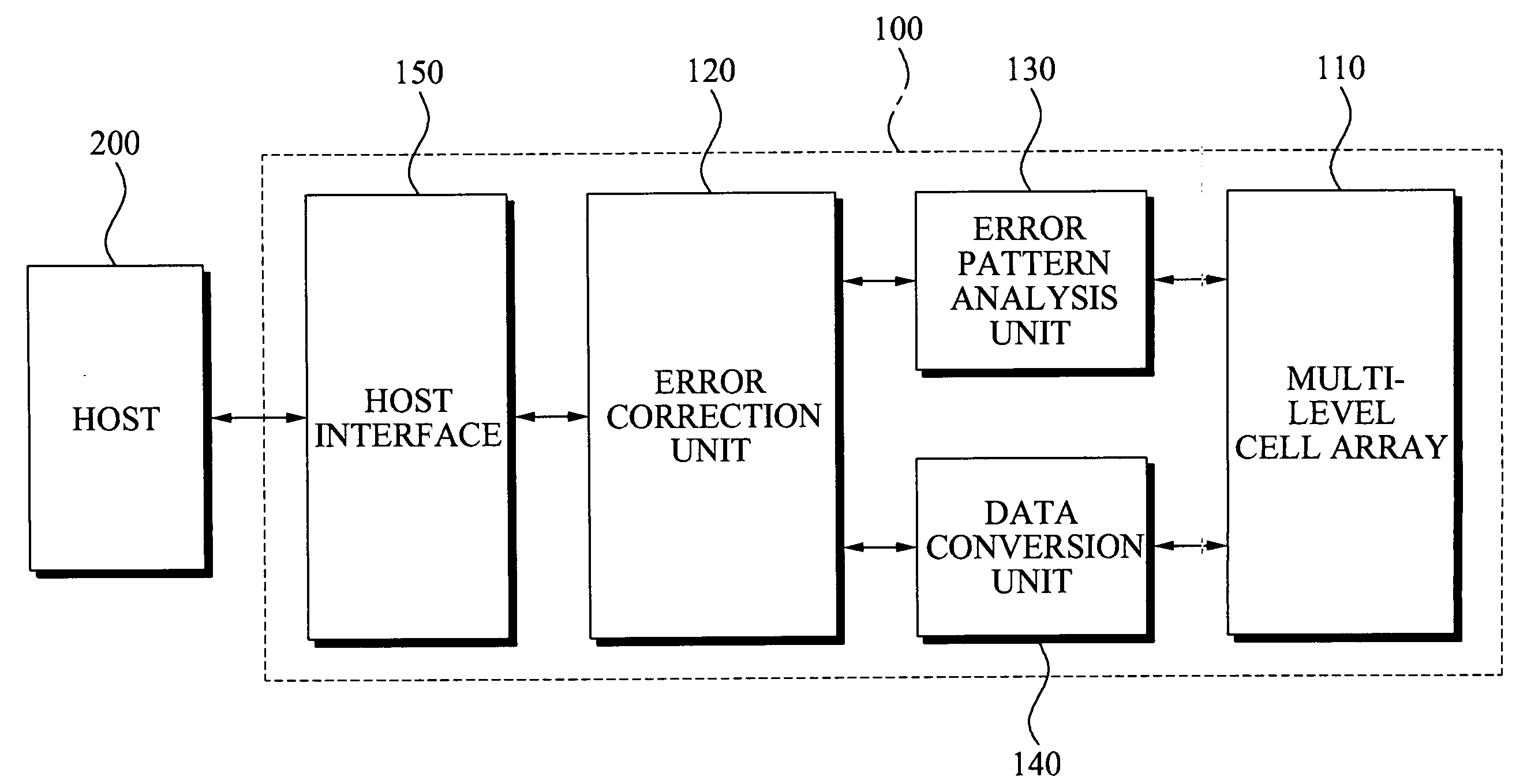
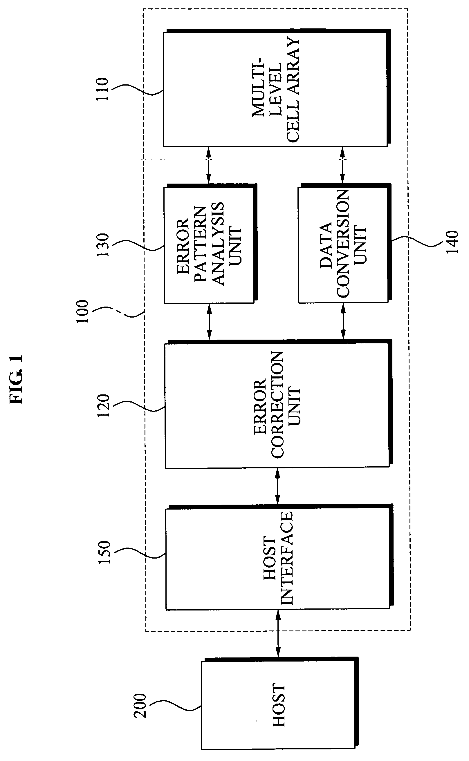
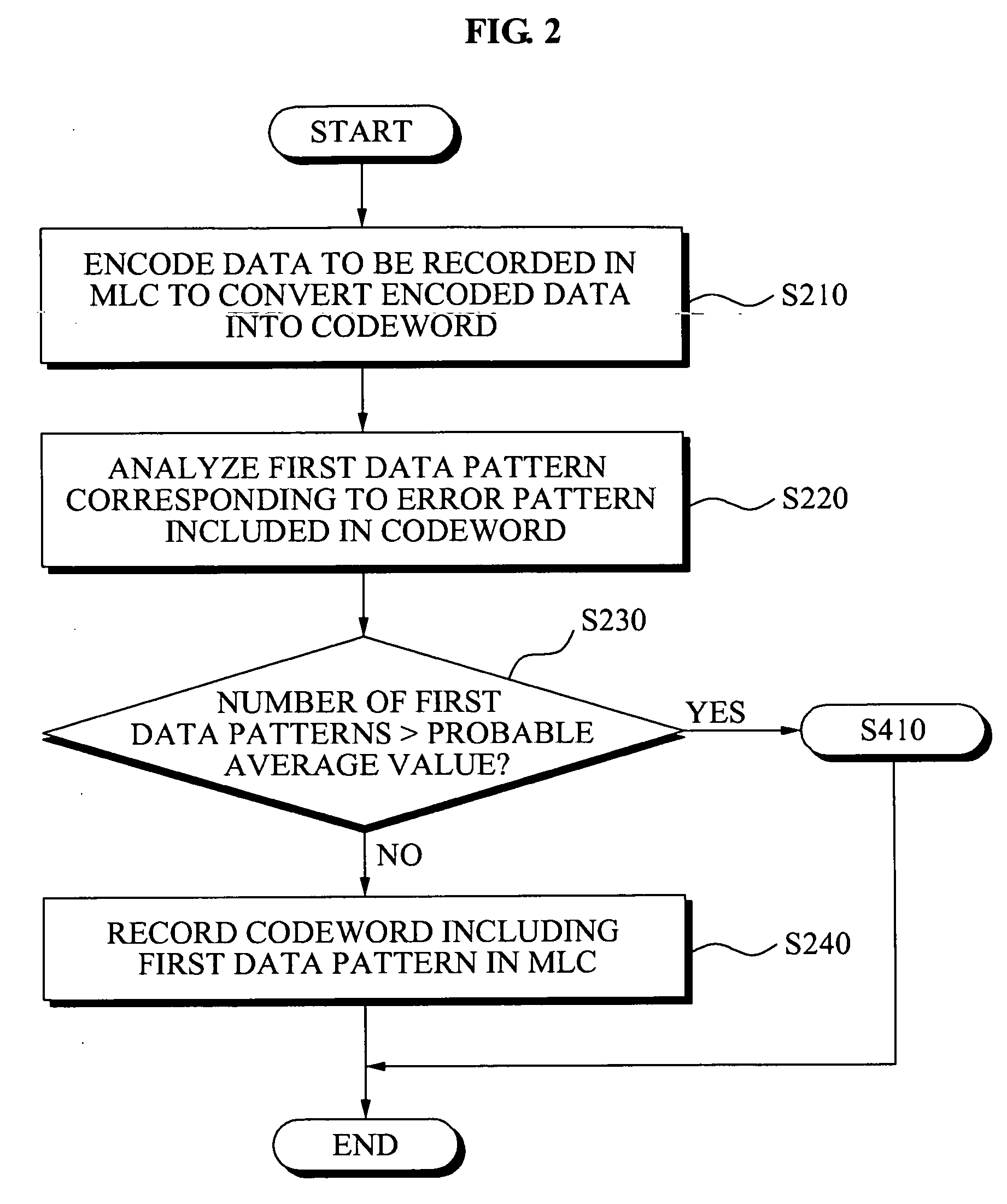
Memory devices and / or methods of storing memory data bits may be provided. A memory device may include a multi-level cell (MLC) array including a plurality of MLCs, an error correction unit configured to encode data to be recorded in an MLC, where the encoded data is converted to convert the encoded data into a codeword, an error pattern analysis unit configured to analyze a first data pattern included in the codeword corresponding to an error pattern included in the codeword and a data conversion unit configured to convert the analyzed first data pattern into a second data pattern. According to the above memory devices and / or methods, it may be possible to efficiently reduce a data error that occurs when the data is stored for a relatively long period of time, thereby improving reliability.

Description

PRIORITY STATEMENT[0001]This application claims priority under 35 U.S.C. §119 to Korean Patent Application No. 10-2008-0048267, filed on May 23, 2008, in the Korean Intellectual Property Office (KIPO), the entire contents of which are incorporated herein by reference.BACKGROUND[0002]1. Field[0003]Example embodiments relate to methods that may store data bits of memory devices. Also, example embodiments relate to multi-level cell (MLC) memory devices or multi-bit cell (MBC) memory devices and / or data bit storage methods that may record / read data bits of the memory devices.[0004]2. Description of Related Art[0005]A multi-level cell (MLC) memory device that may store data of two or more bits in a single memory cell has been proposed in response to a need for higher integration of memory. The MLC memory device may also be referred to as a multi-bit cell (MBC) memory. However, as the number of bits programmed in the single memory cell increases, reliability may deteriorate and a read-fai...

Claims


Application Information

Patent Timeline
IPC IPC(8): H03M13/05G06F11/10
CPCG06F11/1072G11C7/1006G11C11/5642G11C16/26G11C29/00H03M13/13H03M13/611H03M13/27H03M13/2732H03M13/2906H03M13/3707H03M13/3715H03M13/47H03M13/15G11C16/04G11C16/08G11C29/42
Inventor SEOL, KWANG SOOPARK, SUNG ILCHO, KYOUNG LAEJOE, IN SUNG
Owner SAMSUNG ELECTRONICS CO LTD
Learn More