Flow simulation in a well or pipe

a well or well-flow simulation technology, applied in the direction of analogue and hybrid computing, well-logging of electric/magnetic signals, nuclear radiation detection, etc., can solve the problems of insufficient suitability of traditional pressure transient analysis for simulation of the stimulation process of such wells, individual reservoir layers may be very thin, etc., to achieve accurate and efficient numerical solutions

Active Publication Date: 2009-12-03
TOTAL E&P DANMARK AS
View PDF4 Cites 96 Cited by
  • Summary
  • Abstract
  • Description
  • Claims
  • Application Information

AI Technical Summary

Benefits of technology

[0009]It is thus an object of the present invention to provide an accurate and efficient numerical solution strategy for analyzing transient, i.e. time-dependent, aspects during material transport in the above systems, in particular in the context of acid stimulation of long horizontal wells completed in a carbonate reservoir with a CAJ liner.
[0010]According to a first aspect, it has turned out that the accuracy of simulations of fluid transport in a system for stimulating a well in a material formation of a resource reservoir can significantly be improved when the transport model further includes a model of material transport in a predetermined space around said conduit element. Consequently the combined flow in the conduit element such as the liner of a CAJ liner system, and in an annulus surrounding the liner is modelled, thereby providing a more accurate representation of the well-bore geometry which results in an improved modelling accuracy and providing an improved construction and operation of the stimulation system. In particular, incorporation of annulus cells in the model improves the modelling of the displacement of mud by acid, since mud flow in the annulus in the opposite direction compared to the flow inside the liner can be represented correctly.

Problems solved by technology

Furthermore, individual reservoir layers may be very thin, i.e. wells typically penetrate several units.
Traditional pressure transient analysis is not well suited for simulation of the stimulation process of such wells, because they either ignore the varying reservoir properties or omit the flow distribution in the liner, or both.

Method used


Image

  • Flow simulation in a well or pipe
  • Flow simulation in a well or pipe
  • Flow simulation in a well or pipe

Examples


Embodiment Construction

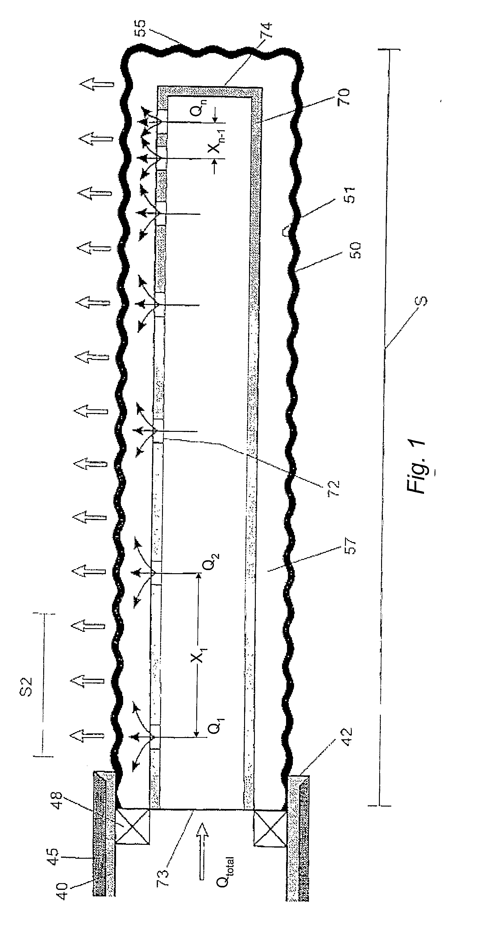
[0050]FIG. 1 shows a schematic cross-sectional view of a bore-hole and the completion of a CAJ liner. In particular, FIG. 1 illustrates the horizontal portion of a well bore 50 for the production of oil or gas from a reservoir. The well bore 50 as such is conventionally established by drilling with drill bits having decreasing operation diameter in a manner known as such and described in e.g. EP1184537.

[0051]When the drill bit has reached the desired reservoir section, a so-called reservoir liner 40 is introduced, and cement is pumped down to form an isolation 45 between the outside of the reservoir liner 40 and the wall of the well bore 50 in the reservoir 1. Then drilling is continued to provide the end section S of the well bore 50 that extends within the reservoir 1 past the end 42 of the reservoir liner 40.

[0052]A stimulation liner / tubing 70 is introduced into the end section S by means of conventional introduction equipment, and the production tubing (not shown) is introduced ...


PUM


Abstract

A method of simulating fluid transport in a system for stimulating a well in a material formation of a resource reservoir, the system comprising a conduit element arranged in said well, the conduit element comprising a conduit wall including one or more openings for discharging a fluid into the material formation surrounding the conduit element; the method comprising establishing and numerically processing a transport model of fluid transport inside the conduit element. The transport model further includes a model of fluid transport in a predetermined space around said conduit element.

Description

TECHNICAL FIELD[0001]Disclosed are methods for simulating material transport in a pipe or well.BACKGROUND AND STATE OF THE ART[0002]Horizontal wells with continuous reservoir sections exceeding 10,000 ft are being used for the development of a number of oil fields, e.g. the laterally extensive low permeability chalk in the Dan / Halfdan oil accumulation as well as on a number of other fields located in the Danish part of the North Sea.[0003]To avoid the risk of a hole collapse as a result of drilling, the wells are typically cased off with intermediate casings, including the reservoir section, denoted the pay zone. In wells with large pressure gradients along the well bore, a traditional completion strategy involves installation of a cemented liner with an inner string, the tubing, extending all the way to the surface. Operational experience has demonstrated that such an approach, known as the Perforate-Stimulate-Isolate (PSI) system, is costly and yields modest well productivity when...

Claims


Application Information

Patent Timeline
Patent Type & Authority Applications(United States)
IPC IPC(8): E21B43/25E21B47/00E21B43/16G06G7/50G06F17/10
CPCE21B43/00E21B43/25G06F2217/34G06F2217/16G06F17/5009G06F2113/14G06F2111/10G06F30/20
Inventor HANSEN, JENS HENRIKMOGENSEN, KRISTIAN
Owner TOTAL E&P DANMARK AS
Why Eureka
Try Eureka