
Spent fuel reprocessing method

Inactive Publication Date: 2009-12-03
KK TOSHIBA
View PDF18 Cites 7 Cited by
  • Summary
  • Abstract
  • Description
  • Claims
  • Application Information

AI Technical Summary

Benefits of technology

[0011]Thus, according to the present invention, it is possible to isolate most of the uranium from spent fuel solution and collect it as light water reactor fuel, while it is possible to collect Pu and minor actinides with U so as to make them utilizable as metal fuel for a fast reactor. As Pu is not collected alone by itself and Pu and minor actinides are collected with U, the present invention can ensure a high degree of nuclear non-proliferability.

Problems solved by technology

Then, the Pu solution and the U solution are put together and subjected to mixture and denitration so that it is not possible to collect Pu alone.
Since U and Pu are temporarily separated from each other in the separation step of the Purex process, nuclear non-proliferability is not absolutely secured.

Method used


Image

  • Spent fuel reprocessing method
  • Spent fuel reprocessing method
  • Spent fuel reprocessing method

Examples


first embodiment

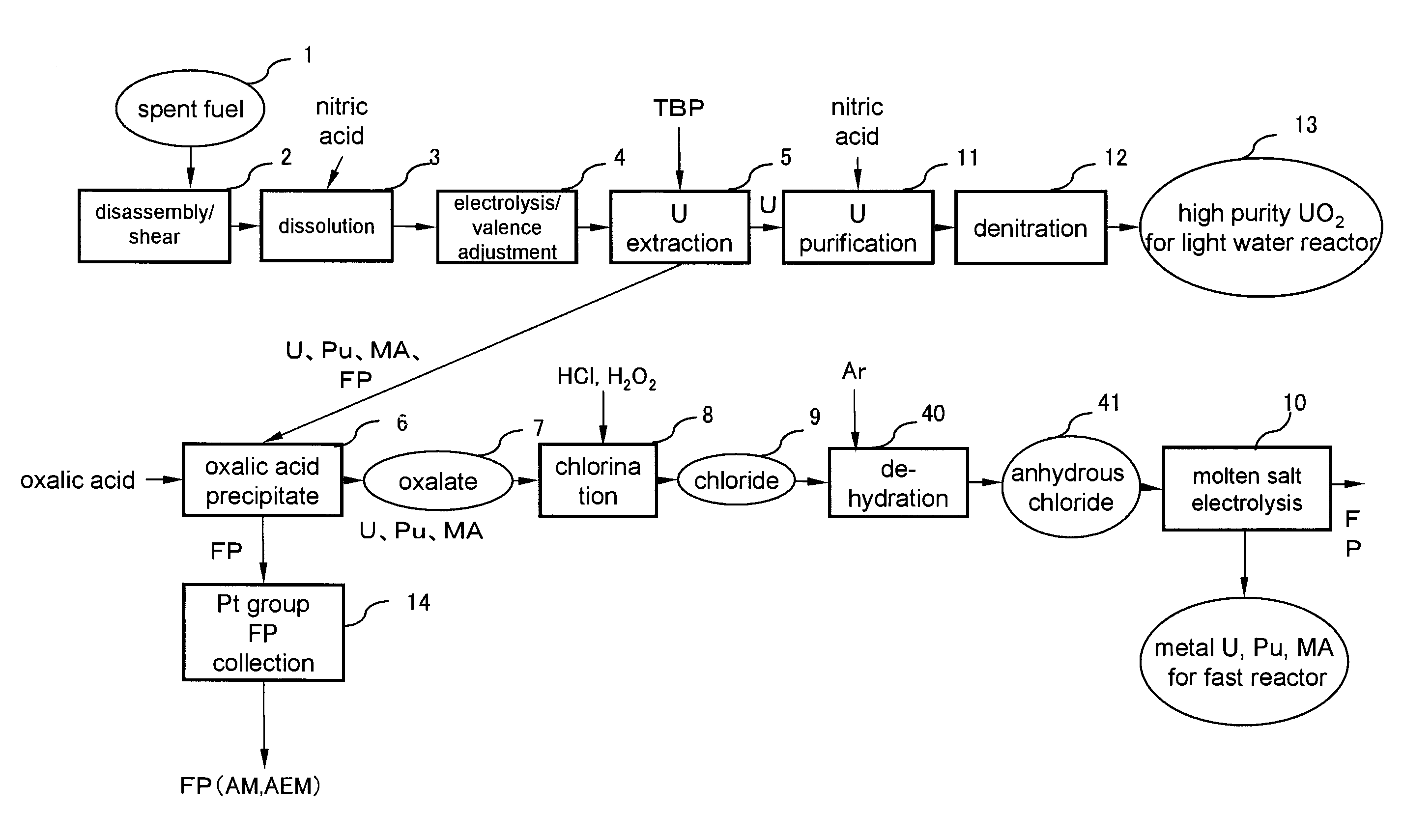
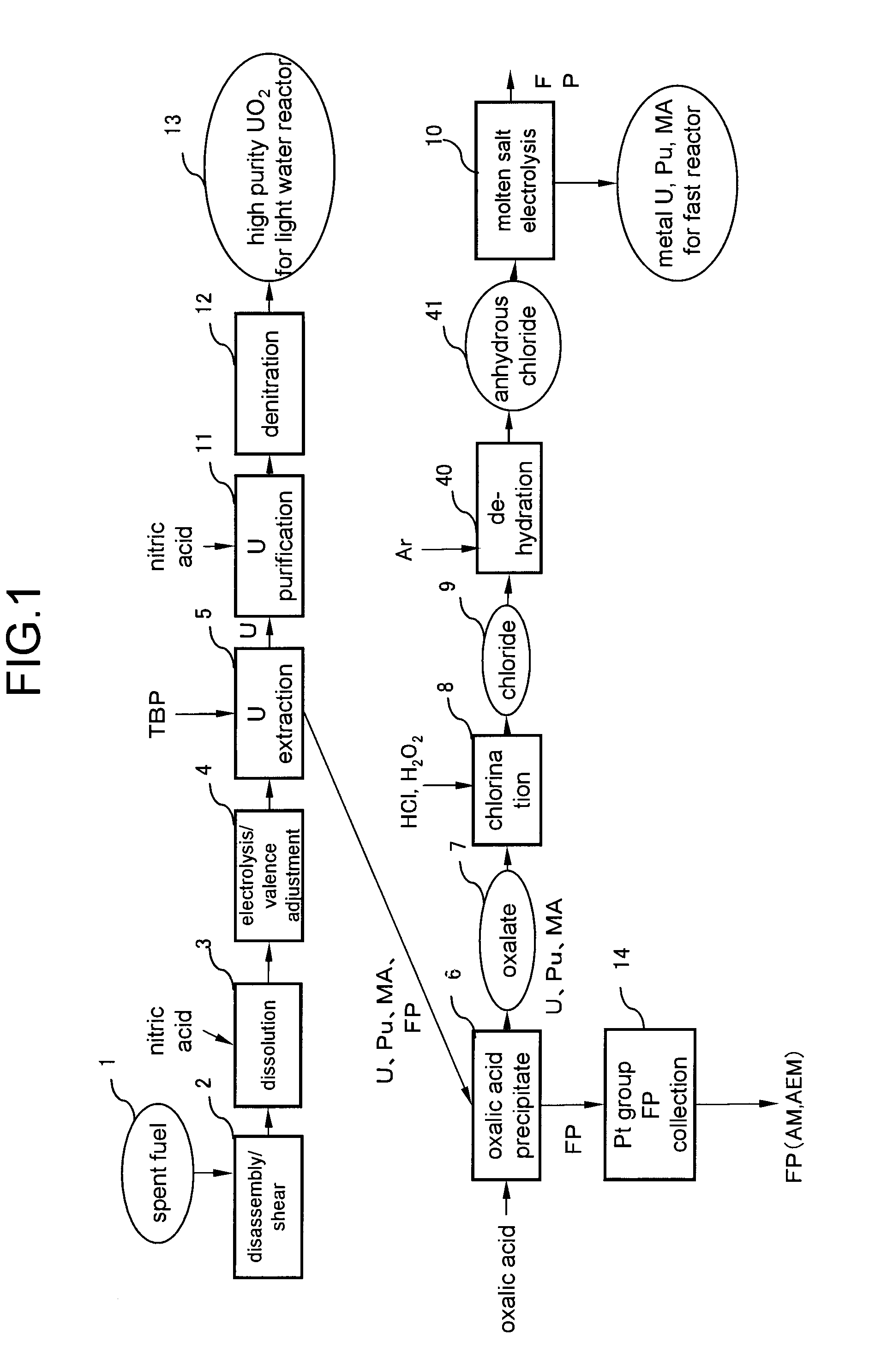
[0020]The first embodiment of spent fuel reprocessing method according to the present invention will be described below by referring to FIGS. 1 and 2.

[0021]FIG. 1 is a flowchart of spent fuel reprocessing method according to a first embodiment of the present invention. Referring to FIG. 1, first, spent oxide fuel 1 is disassembled and sheared in a disassembly / shear step 2. Subsequently, all the spent oxide fuel is dissolved by nitric acid in a dissolution step 3. At this time, U exists in a hexavalent state whereas Pu exists in a tetravalent state.

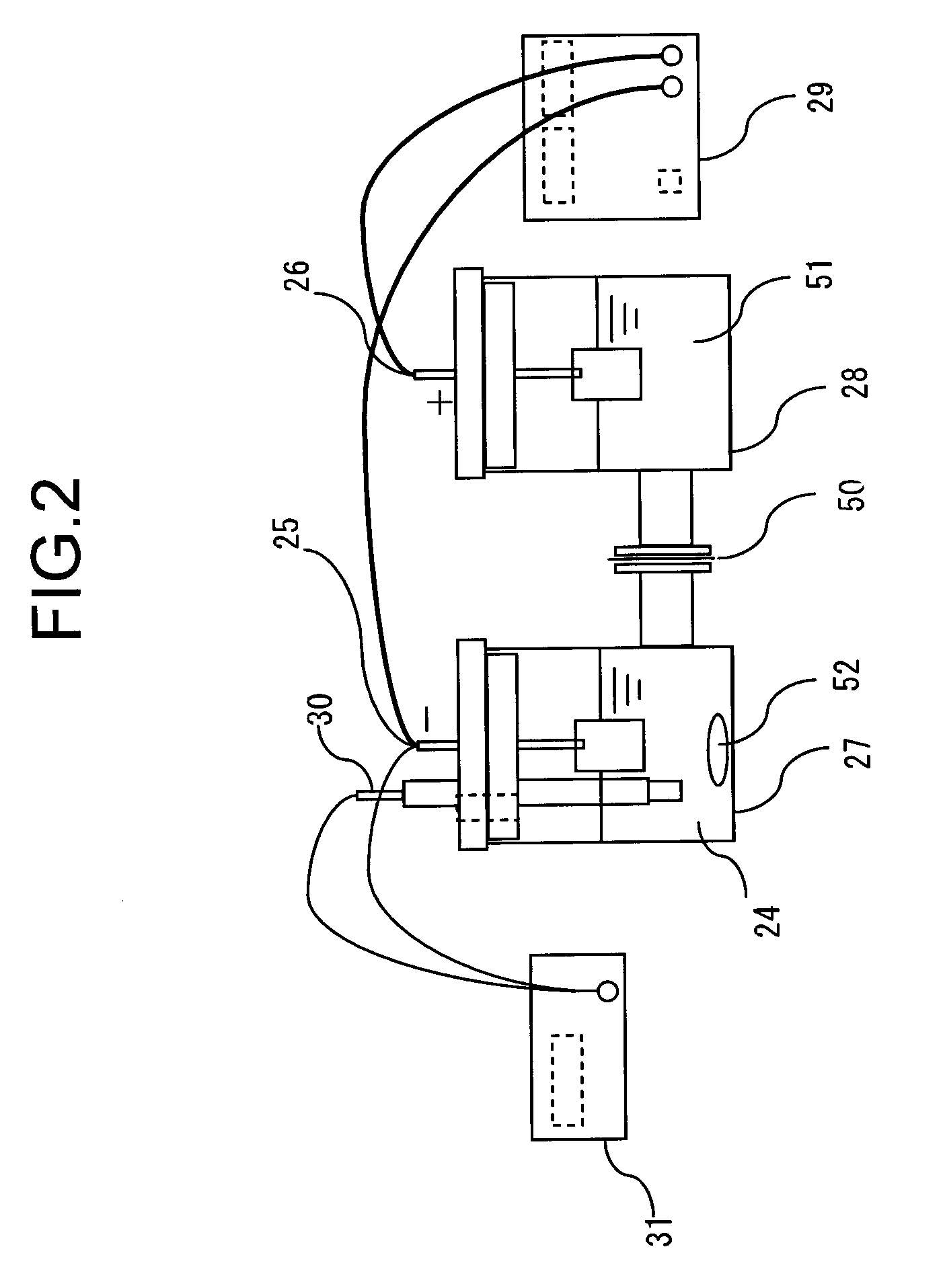
[0022]Thereafter, Pu is electrolytically reduced to trivalent in an electrolysis / valence adjustment step 4. FIG. 2 is a schematic sectional elevational view of an apparatus that can be employed for the electrolysis / valence adjustment step 4 of the first embodiment. More specifically, a cathode chamber 27 and an anode chamber 28 are separated from each other by means of a diaphragm 50 in the apparatus. Catholyte 24 is stored in the cathode ...

second embodiment

[0038]Now, the second embodiment of spent fuel reprocessing method according to the present invention will be described below by referring to FIGS. 5 and 6. The parts of this embodiment that same as or similar to those of the first embodiment are denoted respectively by the same reference symbols and will not be described repeatedly.

[0039]FIG. 5 is a flowchart of spent fuel reprocessing method according to a second embodiment of the present invention. FIG. 6 is a schematic sectional elevational view of an apparatus that can be employed for the electrolysis / reduction step of the second embodiment.

[0040]The sequence down to the oxalic acid precipitation step 6, where the oxalic acid precipitate 7 containing U, Pu, minor actinides and rare earth elements are collected, is same as that of the first embodiment.

[0041]This second embodiment has an oxidation / dehydration step 15 and an electrolysis / reduction step 17 instead of the chlorination step 8, the dehydration step 40 and the molten s...


PUM

PropertyMeasurementUnit
Electric potential / voltageaaaaaaaaaa
Current densityaaaaaaaaaa

Abstract

A spent fuel reprocessing method has a dissolution step of dissolving the spent fuel in nitric acid solution, an electrolysis / valence adjustment step of reducing Pu to trivalent, maintaining the pentavalent of Np, a uranium extraction step of collecting UO2 by bringing the fuel into contact with organic solvent and extracting hexavalent U by means of an extraction agent, an oxalic acid precipitation step of causing MA and the fissure products remaining in the nitric acid solution to precipitate together as oxalic acid precipitate, a chlorination step of converting the oxalic acid precipitate into chlorides by adding hydrochloric acid to the oxalic acid precipitate, a dehydration step of synthetically producing anhydrous chlorides by dehydrating the chlorides in a flow of Ar gas, and a molten salt electrolysis step of dissolving the anhydrous chlorides into molten salt and collecting U, Pu and MA at the cathode by electrolysis.

Description

CROSS REFERENCES TO RELATED APPLICATIONS[0001]This application is based upon and claims the benefits of priority from the prior Japanese Patent Applications No. 2008-143431, filed in the Japanese Patent Office on May 30, 2008, the entire content of which is incorporated herein by reference.BACKGROUND OF THE INVENTION[0002]The present invention relates to a spent fuel reprocessing method comprising a step of collecting uranium (U), plutonium (Pu) and minor actinides (MA) from spent oxide nuclear fuel.[0003]The Purex process is a known typical process for reprocessing spent fuel produced from nuclear power plants so as to refine and collect useful substances contained in the spent fuel in order to reutilize them as fuel and isolate unnecessary fission products. Spent fuel contains alkali metal (AM) elements, alkaline-earth metal (AEM) elements and platinum group elements as fission products (FP) besides transuranic elements (TRU) such as uranium and plutonium.[0004]In the Purex proces...

Claims


Application Information

Patent Timeline
IPC IPC(8): C25C1/22C25B1/00
CPCG21C19/46C25C1/22C25C3/34Y02E30/30Y02P10/20Y02W30/50G21F9/06
Inventor MIZUGUCHI, KOJIFUJITA, REIKOFUSE, KOUKINAKAMURA, HITOSHIUTSUNOMIYA, KAZUHIROKAWABE, AKIHIRO
Owner KK TOSHIBA
Learn More