Reverse current stopping circuit of synchronous rectification type DC-DC Converter

Active Publication Date: 2009-12-03
FUJI ELECTRIC CO LTD
View PDF6 Cites 72 Cited by
  • Summary
  • Abstract
  • Description
  • Claims
  • Application Information

AI Technical Summary

Benefits of technology

[0017]According to the present invention, even if there is a wide variation in input offset voltage of the comparator, the offset voltage can be increased or decreas

Problems solved by technology

Particularly in a high-current DC-DC converter, even a very small detection error of a drain-to-source voltage Vds becomes a large current error due to a low ON resistance of the synchronous rectification MOSFET Mn.
Thus, it is unlikely that a reverse current can be stopped.
However, there is no suggestion about how to increase or decrease an offset voltage to avoid influence of the variation in input offset voltage of the comparator so as to adjust the threshold level of the comparator to a point where no reverse current exists.
However, there is no suggestion about how to increase or decrease an offset voltage to avoid influen

Method used


Image

  • Reverse current stopping circuit of synchronous rectification type DC-DC Converter
  • Reverse current stopping circuit of synchronous rectification type DC-DC Converter
  • Reverse current stopping circuit of synchronous rectification type DC-DC Converter

Examples


first embodiment

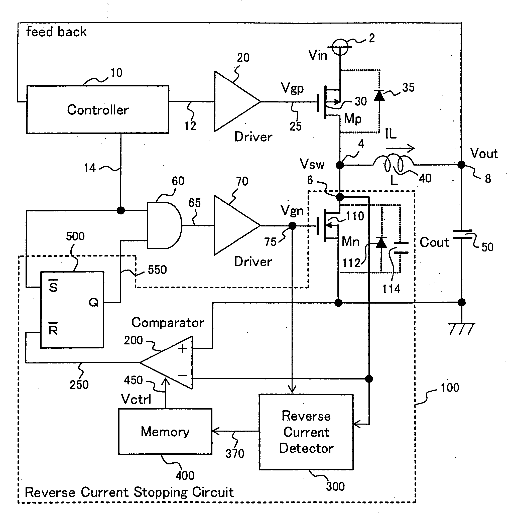
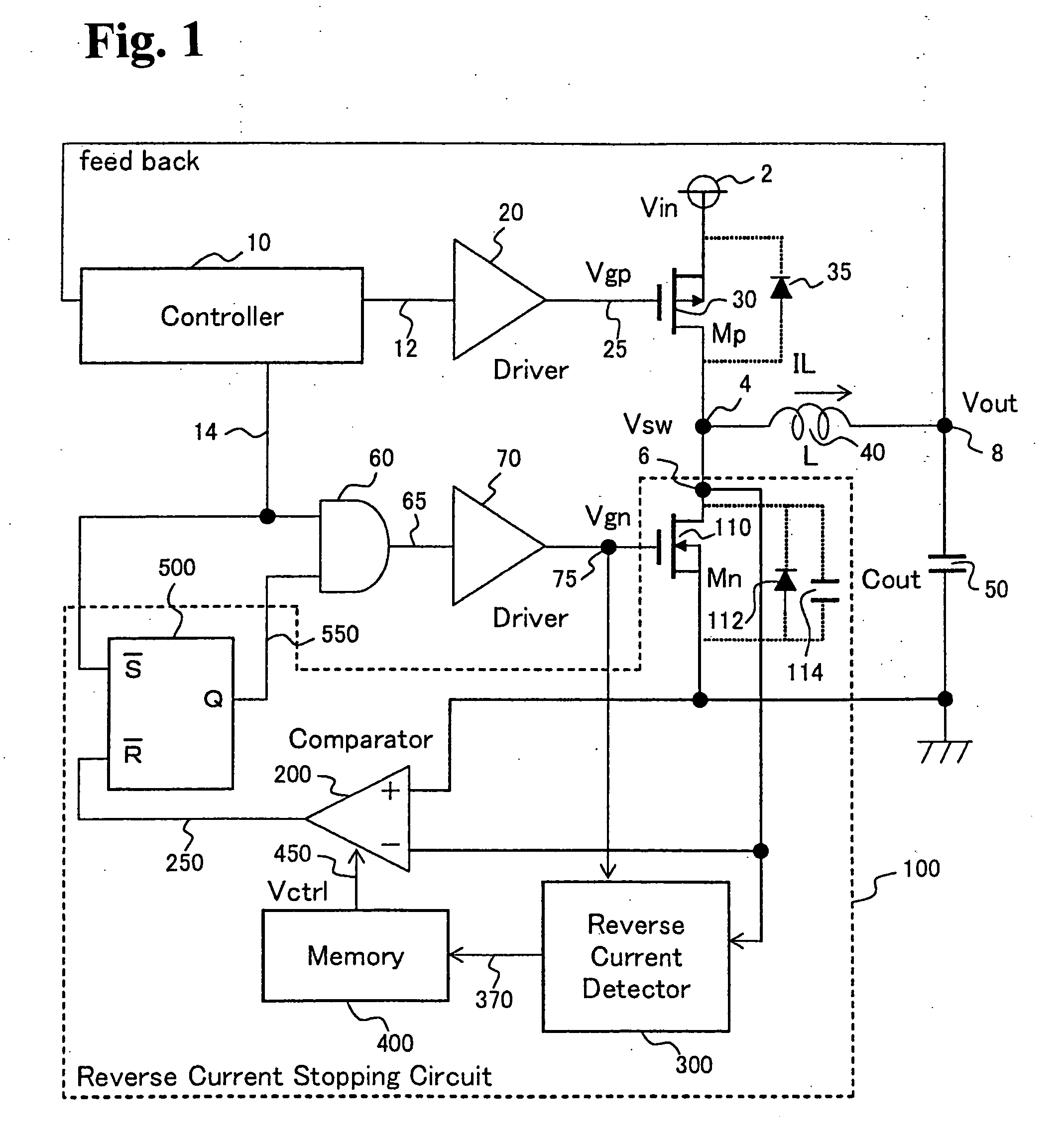
[0037]FIG. 3 is a diagram showing a main portion of a reverse current stopping circuit of a synchronous rectification type DC-DC converter according to a first embodiment of the present invention. As shown in FIG. 1, the reverse current stopping circuit of the synchronous rectification type DC-DC converter includes the comparator (200), the reverse current detector circuit (300), the memory (400), the flip-flop (500) and the Mn (110). Of those, the main portion of the reverse current stopping circuit shown in FIG. 3 relates to the configurations of the comparator (200), the reverse current detector circuit (300) and the memory (400).

[0038]The reverse current detector circuit (300) includes an RS latch (310), a delay circuit (320), a logic circuit and a charge pump (350). The RS latch (310) holds the leading edge of the Vsw (4). The delay circuit (320) delays the trailing edge of the Vgn (75) by the predetermined time Td. The logic circuit has a NAND circuit (330) and a NOR circuit (...

second embodiment

[0047]FIG. 6 is a diagram showing a main portion of a reverse current stopping circuit of a synchronous rectification type DC-DC converter according to a second embodiment of the present invention. As shown in FIG. 1, the reverse current stopping circuit of the synchronous rectification type DC-DC converter includes the comparator (200), a reverse current detector circuit (designated by 600 in FIG. 6 though 300 in FIG. 1), the memory (400), the flip-flop (500) and the Mn (110). Of those, the main portion of the reverse current stopping circuit shown in FIG. 6 relates to the configurations of the comparator (200), the reverse current detector circuit (600) and the memory (400).

[0048]The reverse current detector circuit (600) includes an RS latch (610), a delay circuit (620), and an up-down counter (630). The RS latch (610) holds the leading edge of the Vsw (4). The delay circuit (620) delays the trailing edge of the Vgn (75) by the predetermined time Td. The up-down counter (630) cou...


PUM


Abstract

A reverse current stopping circuit includes a synchronous rectification device, a comparator for detecting a reverse current of an inductor, the synchronous rectification device being turned off when the reverse current is detected by the comparator, a reverse current detector circuit for detecting a switching terminal voltage after the synchronous rectification device is turned off, thereby determining a value of the inductor current to decide whether the inductor current is flowing in a reverse direction or a forward direction, and a memory unit for receiving a predetermined output signal from the reverse current detector circuit in accordance with a result of the reverse current detector circuit, and outputting a control signal for an offset voltage in accordance with the predetermined output signal. The offset voltage is changed in accordance with the control signal so as to adjust the inductor current to zero when the synchronous rectification device is turned off.

Description

BACKGROUND OF THE INVENTION[0001]The present invention relates to a reverse current stopping circuit of a synchronous rectification type DC-DC converter, which detects a reverse current of an inductor current of an inductor located in an output portion of the synchronous rectification type DC-DC converter and stops the reverse current.[0002]FIG. 7 is a diagram showing the configuration of a reverse current stopping circuit of a synchronous rectification type DC-DC converter according to a conventional art. The synchronous rectification type DC-DC converter uses a synchronous rectification MOSFET (Metal Oxide Semiconductor Field Effect Transistor) Mn in place of a freewheeling diode (not shown) so as to reduce conduction loss, thereby improving efficiency under heavy load conditions. However, the MOSFET used as a synchronous rectification device allows a current to flow therein in a reverse direction. Therefore, when a current is conducted to a switching device Mp (30) and the synchr...

Claims


Application Information

Patent Timeline
IPC IPC(8): G05F1/10
CPCY02B70/1466H02M3/1588Y02B70/10
Inventor YAMADA, KOUHEI
Owner FUJI ELECTRIC CO LTD
Why Eureka
Try Eureka