Magnetic field probe and method for manufacturing the same

a magnetic field and probe technology, applied in the field of magnetic field probes, can solve the problems of limiting the signal lifetime, affecting so as to improve the accuracy of mr spectroscopy and mr imaging methods.

Active Publication Date: 2009-12-03
UNIV ZURICH +1
View PDF7 Cites 37 Cited by
  • Summary
  • Abstract
  • Description
  • Claims
  • Application Information

AI Technical Summary

Benefits of technology

[0011]It is the principal object of the present invention to overcome the limitations and disadvantages of currently known magnetic field probes for magnetic resonance applications. A further object of the present invention is to improve the accuracy of MR spectroscopy and MR imaging methods.

Problems solved by technology

Despite continued advances in magnetic resonance (MR) instrumentation, imperfections in the magnetic field evolution still hamper numerous MR procedures.
However, to do so these errors need to be accurately known.
A key challenge in designing magnetic field probes based on magnetic resonance (henceforth also called “MR-based magnetic field probes”) is obtaining strong and long-lived signals from probe samples that are small enough to avoid dephasing by externally applied gradients.
However, nearby material interfaces tend to induce magnetic field variations in the probe sample, thus limiting its signal lifetime.
For example, when using water as the probe substance by placing a small water droplet in a thin glass capillary surrounded just by air and a tightly wound copper solenoid, impractically short signal lifetimes of less than 10 ms are achieved.
A disadvantage of the above described magnetic field probe is due to the fact that the magnetic susceptibilities of copper (−9.65 ppm) and FC-77 (approximately −8 ppm) are by no means identical.
This residual susceptibility mismatch causes an undesirable shortening of the probe's resonance signal.
A further disadvantage is caused by the fact that FC-77 is a liquid at room temperature, which is impractical for the purpose of enclosing the complete probe.
The main factor limiting sensitivity for high-resolution applications has been reported by Massin, loc. cit. as being probe-induced static magnetic field distortions; these are mainly caused by differences in bulk magnetic susceptibility of materials composing the probe.

Method used


Image

  • Magnetic field probe and method for manufacturing the same
  • Magnetic field probe and method for manufacturing the same
  • Magnetic field probe and method for manufacturing the same

Examples


example 1

Magnetic Field Probe for Nuclear Magnetic Resonance Applications

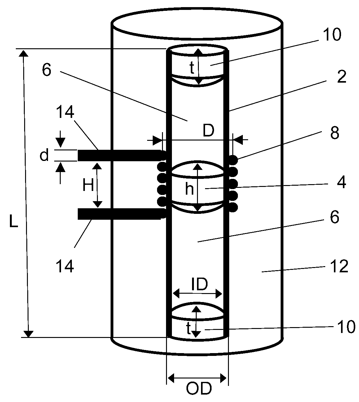
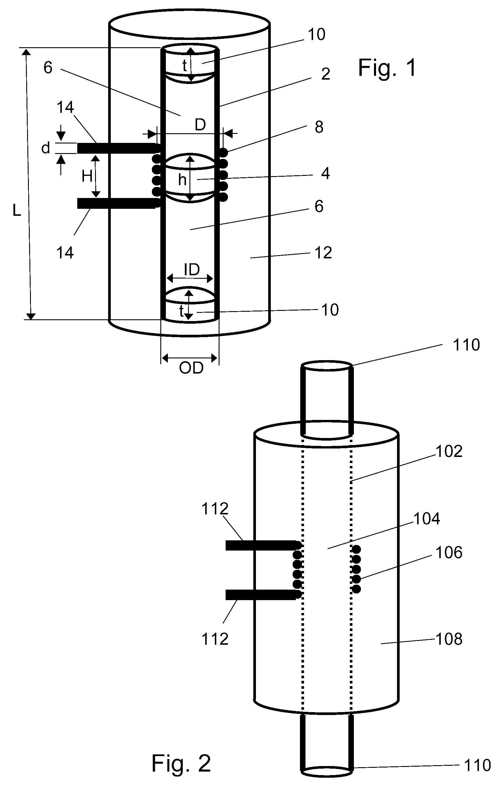
[0092]This example refers to a magnetic field probe as the one schematically shown in FIG. 1, which is useful as a sensor for detecting local magnetic field intensities. In particular, a plurality of such magnetic field probes may be implemented in a NMR system such as the one described in EP 1 582 886 A1, the contents of which are incorporated herein by reference. It will be understood that such a system is operated with a certain static magnetic field and at a certain RF frequency, henceforth called the operating frequency. It will also be understood that the operating frequency is related to the strength of the static magnetic field and to the type of resonating nucleus.

Manufacturing of Magnetic Field Probes with Solid-State Susceptibility Matching

[0093]The task of the magnetic field probe is to yield strong and long-lived NMR signals from a well-defined position in space. To meet the latter requirement, the sample i...

example 2

Nuclear Magnetic Resonance Probe

[0110]This example refers to a NMR probe as the one schematically shown in FIG. 2. Such probes are useful e.g. for obtaining NMR spectra or NMR intensity data from small liquid samples, as described in Olson D. L. et al., Science; 270 No. 5244 (1995) pp. 1967-1970, the contents of which are incorporated herein by reference. The probe described here includes a jacket whose magnetic susceptibility can be accurately matched to that of the solenoid coil used for signal detection. In this fashion the solenoid is prevented from causing magnetic field distortions in the sample. As a consequence the solenoid can be mounted more closely to the sample, using a sample container with a thinner wall, which leads to significantly enhanced overall sensitivity.

example 3

Nuclear Magnetic Resonance Probe

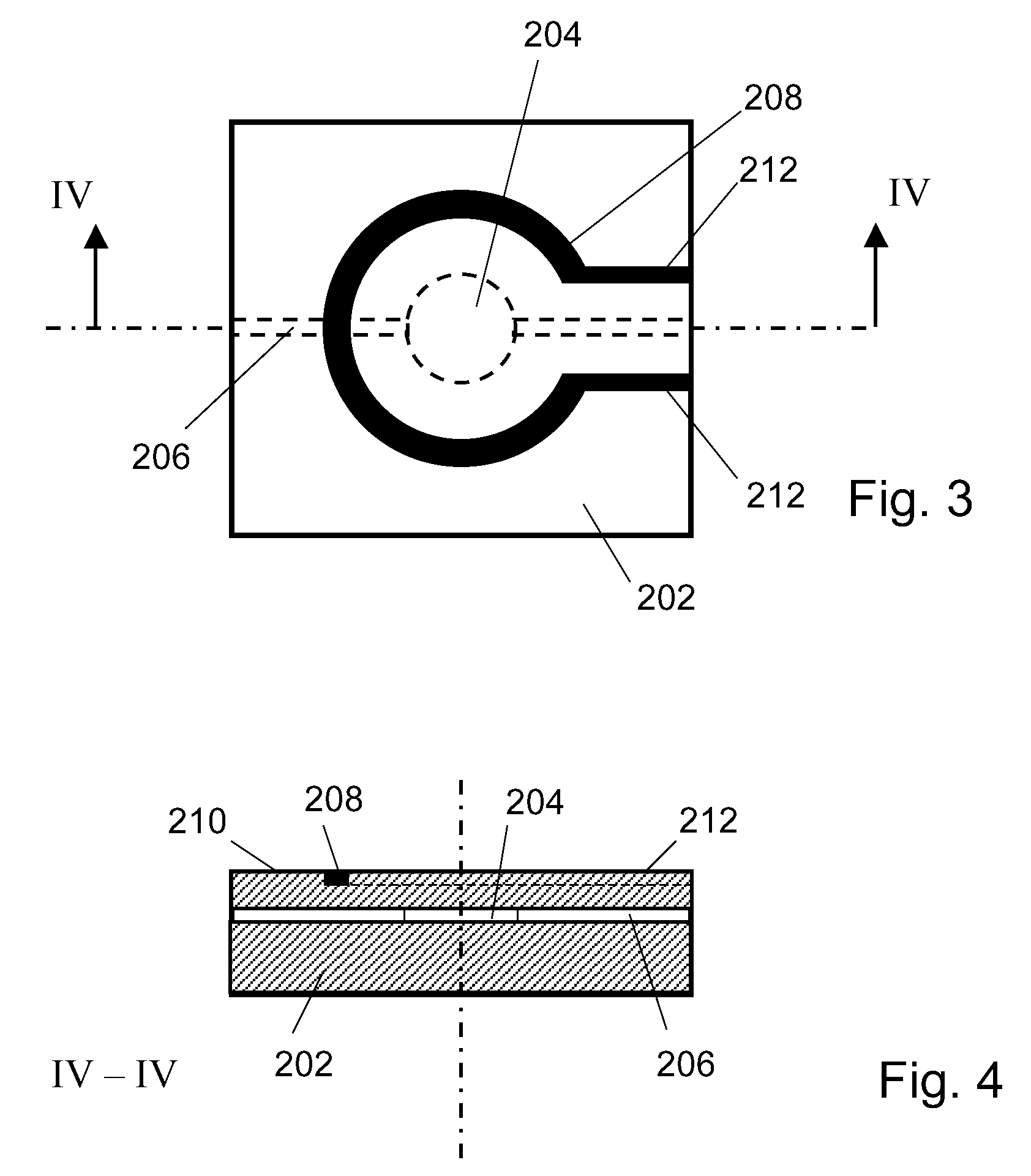
[0111]This example refers to a NMR probe as the one schematically shown in FIGS. 3 and 4. Such probes are useful e.g. for obtaining NMR spectra or NMR intensity data from small liquid samples, as described in Massin, loc. cit., the contents of which are incorporated herein by reference. It will be understood that the electrically conductive structure shown in FIGS. 3 and 4 as a simple loop may be replaced by other structures, depending on the particular application.

[0112]By virtue of the fact that in the probe described here the magnetic susceptibility of the probe body can be accurately matched to the magnetic susceptibility of the sample contained therein, the main factor limiting the sensitivity of the NMR probe described by Massin, loc. cit. for high-resolution applications has been significantly reduced.


PUM


Abstract

A magnetic field probe comprises a sample (4) that exhibits magnetic resonance at an operating frequency, an electrically conductive structure (8) surrounding the sample for receiving a magnetic resonance signal therefrom, and a solid jacket (12) encasing the sample and the conductive structure. The jacket is made of a hardened two-component epoxy system containing a paramagnetic dopant dissolved therein, with the concentration of the dopant being chosen such that the jacket has a magnetic susceptibility that is substantially identical to the magnetic susceptibility of the conductive structure.

Description

TECHNICAL FIELD OF THE INVENTION[0001]The present invention relates to a magnetic field probe according to the preamble of claim 1. Furthermore, the invention relates to a method for manufacturing such a magnetic field probe and to a nuclear magnetic resonance imaging apparatus comprising such a field probe. Moreover, the invention relates to nuclear magnetic resonance probes according to the preambles of claims 18 and 19. Still further, the invention relates to the use of a doped two-component epoxy system.BACKGROUND OF THE INVENTION[0002]Despite continued advances in magnetic resonance (MR) instrumentation, imperfections in the magnetic field evolution still hamper numerous MR procedures. Field perturbations are caused by a range of mechanisms, including eddy currents, limited gradient bandwidth, and heating effects. Often such errors can be addressed by means of signal processing. However, to do so these errors need to be accurately known. Reproducible field perturbations can be ...

Claims


Application Information

Patent Timeline
Patent Type & Authority Applications(United States)
IPC IPC(8): G01R33/44G01R1/06
CPCG01R33/24G01R33/56536G01R33/34053G01R33/34007
Inventor PRUESSMANN, KLAASBARMET, CHRISTOPHDE ZANCHE, NICOLA
Owner UNIV ZURICH
Why Eureka
Try Eureka