
Prismatic battery

a technology of prismatic batteries and outer cans, applied in the field of prismatic batteries, can solve the problems of affecting the manufacturing efficiency of prismatic batteries, affecting the volumetric efficiency, and affecting the edge of the battery outer can, and achieve the effect of favorable heat resistance and high strength

Active Publication Date: 2009-12-03
SANYO ELECTRIC CO LTD
View PDF2 Cites 19 Cited by
  • Summary
  • Abstract
  • Description
  • Claims
  • Application Information

AI Technical Summary

Benefits of technology

[0017]An advantage of some aspects of the present invention is to provide a prismatic battery having favorable insertability of the flat electrode assembly to the battery outer can by improving the shape of the projection for positioning formed on the positive electrode collector or the negative electrode collector, and further, preventing short-circuiting between the positive electrode collector or the negative electrode collector and the battery outer can even if the center line of the inserted flat electrode assembly deviates from the center line of the battery outer can in the width direction, and being suitable for EVs and HEVs with excellent safety.

Problems solved by technology

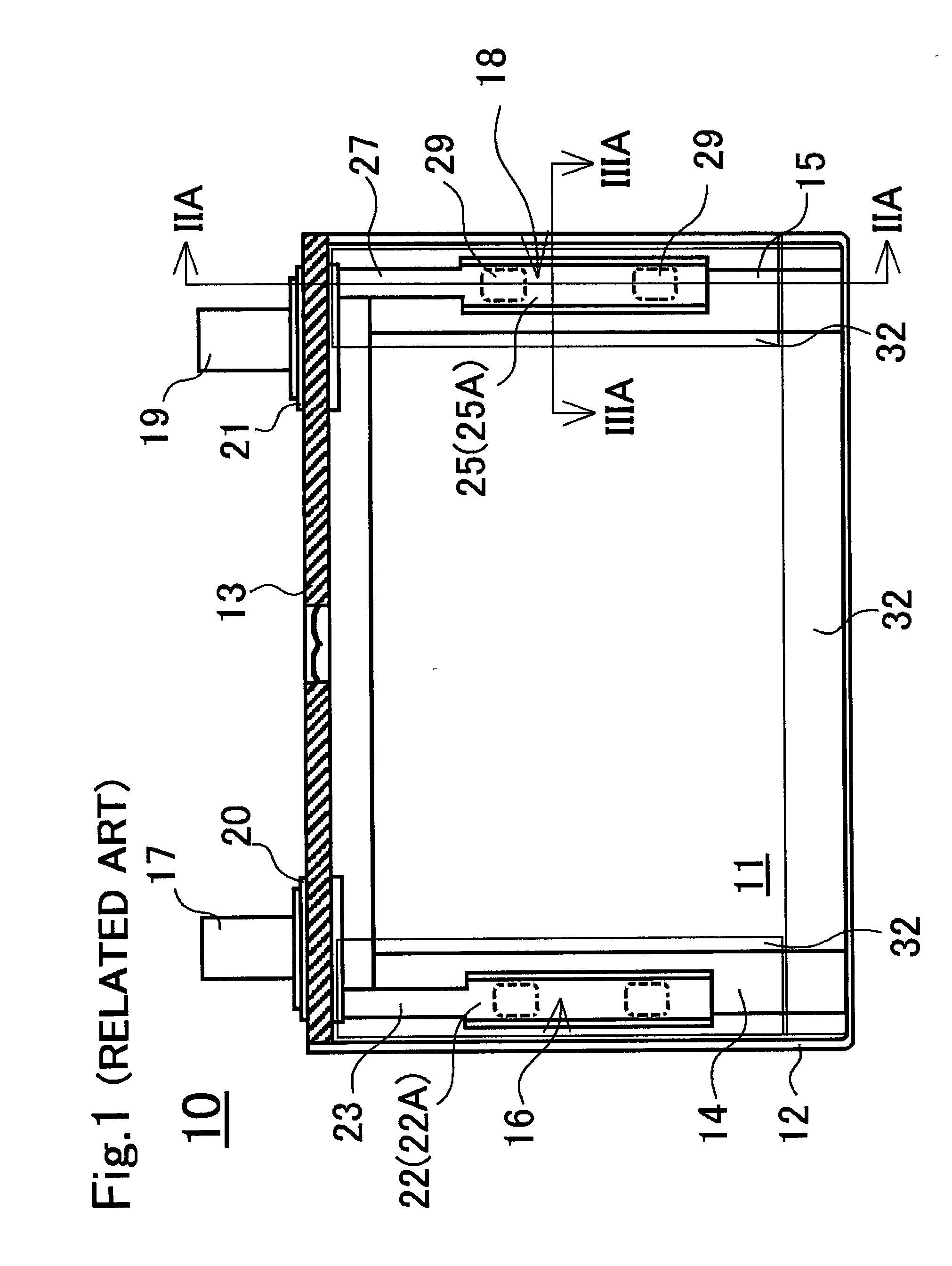
When housing the flat electrode assembly fabricated as described above into a prismatic battery outer can made of metal, the flat electrode assembly can contact the edge of the battery outer can and may be damaged.
Thus, insertability of the flat electrode assembly 83 to the can is degraded and affects the manufacturing efficiency of the prismatic battery.
Thus, using a thin insulating film as an insulating material is difficult, and this also leads to degradation of the volumetric efficiency.
In addition, providing the resin projecting piece 96 as shown in FIG. 8B in the case body 94 not only leads to degradation of the volumetric efficiency, but adversely affects the manufacturing efficiency of batteries or the like.
Thus, simply adopting the current collecting method of the battery or the capacitor 90 shown in JP-A-2000-150306 for fixing flat electrode assemblies of the prismatic batteries for EVs or HEVs is difficult.

Method used


Image

  • Prismatic battery
  • Prismatic battery
  • Prismatic battery

Examples


first working example

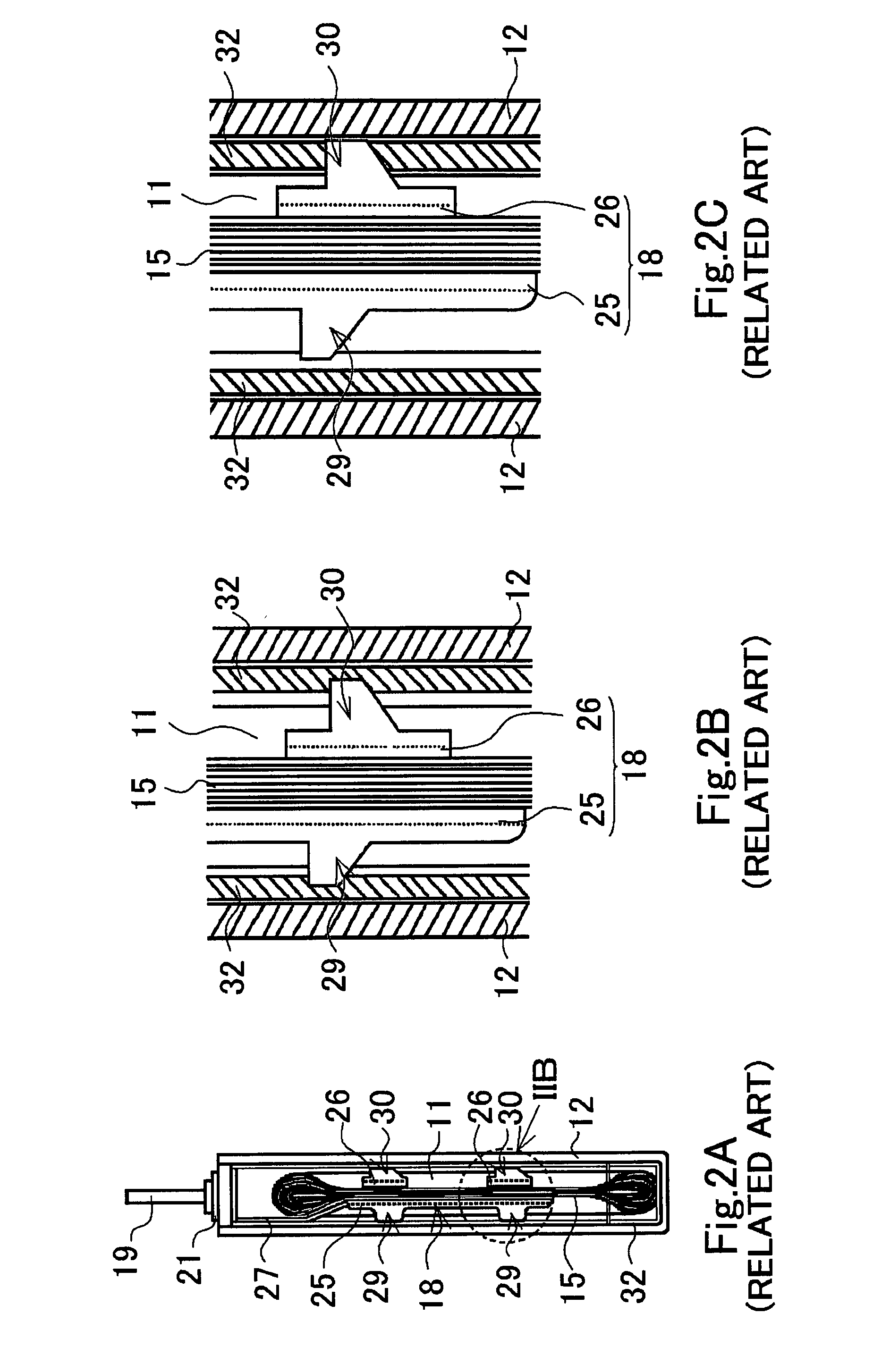
[0060]A structure of a fixing portion of the prismatic battery of the first working example will be explained with reference to FIG. 3A and FIG. 3B. In the prismatic battery of the first working example, since the positive electrode collector member 16 forming the fixing portion on the positive electrode side and the negative electrode collector member 18 forming the fixing portion on the negative electrode side have the same structure, the negative electrode collector member 18 forming the fixing portion on the negative side will be explained in detail, and an explanation of a structure of the positive electrode collector member 16 will be omitted (hereinafter, the same is true for the second working example and the third working example).

[0061]The negative electrode collector member 18 of the prismatic battery of the first working example includes a pair of negative electrode collectors 25A and 25B having a similar shape. Both of the negative electrode collectors 25A and 25B are f...

second working example

[0064]A structure of a fixing portion of the prismatic battery of the second working example will be explained with reference to FIG. 4A and FIG. 4B. The negative electrode collector member 18 of the prismatic battery of the second working example is, like the fixing portion of the first comparative example, composed of the negative electrode collector 25 and the two negative electrode receiving portions 26. On the surface of the negative electrode collector 25, the projection 29 is formed on two locations. On the two negative electrode collector receiving portions 26, the projections 30 are formed, respectively. The projections 29 formed on two locations on the surface of the negative electrode collector 25 includes a first projection 29a on the surface side of the negative electrode collector 25 having a large area, and a second projection 29b formed on the surface of the first projection 29a and having a smaller area than the first projection. Also, the projection 30 formed on th...

third working example

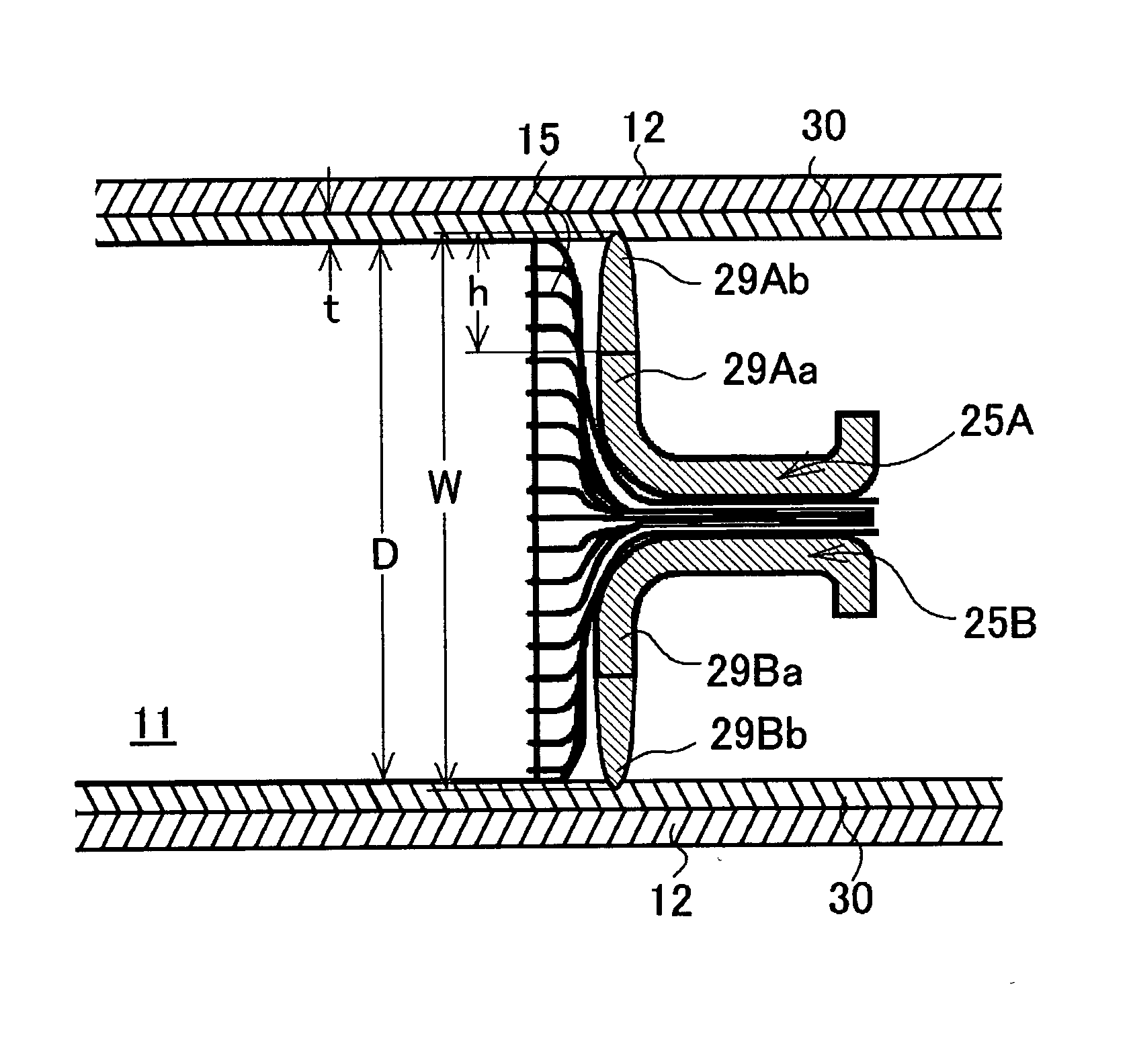
[0068]A structure of a fixing portion of the prismatic battery of the third working example will be explained with reference to FIG. 5A and FIG. 5B. The negative electrode collector member 18 of the prismatic battery of the third working example is the same as that of the prismatic battery of the first working example in the point that both of the negative electrode collectors 25A and 25B are folded and are erect from the negative electrode substrate exposed portion 15 side, and formed with the first projections 29Aa and 29Ba that do not project from the flat electrode assembly 11 towards the battery outer can 12 side, and that the second projections 29Ab and 29Bb are formed on the tip portions of the first projections 29Aa and 29Ba so as the second projections 29Ab and 29Bb project from the flat electrode assembly 11. On the other hand, the structure of the negative electrode collector member 18 of the prismatic battery of the third working example is different from that of the neg...


PUM


Abstract

A prismatic battery is provided with a fixing portion composed of projections 29Aa and 29Ba for fixing the position of a flat electrode assembly 11 and a battery outer can 12 by contacting with an insulating sheet 32 on at least one of a positive electrode collector member 16 and a negative electrode collector member 18. The insulating sheet 32 is provided between the projections 29Aa, 29Ba and the battery outer can 12. Tips 29Ab and 29Bb of the projections 29Aa and 29Ba project from the flat electrode assembly 11 towards the battery outer can 12 side. The height of the projections is smaller than the thickness of the insulating sheet 32. This prevents short-circuiting between the positive electrode collector member or the negative electrode collector member, and the battery outer can. Thus, a prismatic battery suitable for EVs and HEVs with excellent safety can be obtained.

Description

TECHNICAL FIELD[0001]The present invention relates to prismatic batteries such as nonaqueous electrolyte secondary batteries and nickel-hydrogen batteries. More particularly, the invention relates to a prismatic battery which has a flat electrode assembly provided with a positive electrode substrate exposed portion at one end and a negative electrode substrate exposed portion at the other and housed inside a prismatic battery outer can.BACKGROUND ART[0002]Alkaline secondary batteries represented by nickel-hydrogen batteries and nonaqueous electrolyte secondary batteries represented by lithium ion batteries are widely used as power sources for cellular phones, portable computers, portable music players and other portable electronic devices. As curbs on emissions of carbon dioxide and other substances have been strengthened against a background of growing movements for environmental protection, in the automobile world there is now vigorous development of electric vehicles (EVs) and hy...

Claims


Application Information

Patent Timeline
IPC IPC(8): H01M6/12H01M10/04H01M10/0585H01M10/0587H01M50/417H01M50/469H01M50/474H01M50/486H01M50/536H01M50/538H01M50/586H01M50/593
CPCH01M2/14H01M2/1653H01M2/18H01M10/0587H01M2/34H01M10/0585H01M2/263Y02E60/10H01M50/538Y02P70/50H01M50/486H01M50/417H01M50/593H01M50/586H01M50/474H01M50/536H01M50/469H01M2220/20H01M50/59H01M50/414H01M50/103Y02T10/70
Inventor NANSAKA, KENJIYAMAUCHI, YASUHIRO
Owner SANYO ELECTRIC CO LTD
Learn More