Vehicle Transaxle System

a transaxle and vehicle technology, applied in the direction of fluid couplings, couplings, transportation and packaging, etc., can solve the problems of insufficient efficiency of power transmission, insufficient size and cost of conventional transaxle units, and the inability to operate the sub-speed-changing manipulator for operating the sub-speed-changing transmission. to achieve the effect of sufficient power transmission efficiency

Active Publication Date: 2009-12-10
KANZAKI KOKYUKOKI MFG
View PDF12 Cites 14 Cited by
  • Summary
  • Abstract
  • Description
  • Claims
  • Application Information

AI Technical Summary

Benefits of technology

[0007]A first object of the invention is to provide a vehicle transaxle system for a vehicle, especially, for a working vehicle, the vehicle transaxle system including right and left hydraulic transaxle units individually driving respective right and left axles, wherein each of the transaxle units includes a hydrostatic transmission for driving the axle without an additional sub speed-changing transmission interposed between the hydrostatic transmission and the axle, however, it ensures a sufficient efficiency in power transmission to the axle for a normal high-speed traveling of the vehicle (without work).

Problems solved by technology

Even if the maximum displacement of the hydraulic pump is sufficient to ensure a high torque traveling of the vehicle at work, it may be insufficient to ensure a required efficient power transmission for normal high-speed traveling of the vehicle without work.
However, the conventional transaxle unit is expanded in size and is expensive because of the arrangement of the sub speed-changing transmission.
Further, a sub speed-changing manipulator for operating the sub speed-changing transmission may be wrongly operated during traveling of the vehicle.
For example, although a skilled operator can shift the sub speed-changing manipulator to a high speed setting position at an appropriate timing during traveling of the vehicle at work so as to improve the working efficiency, the operation of the sub speed-changing manipulator is too difficult for an unskilled operator to judge a timing for shifting the sub speed-changing manipulator to the high speed setting position, so that the unskilled operator may shift the sub speed-changing manipulator to the high speed setting position at a wrong timing so as to unexpectedly accelerate the vehicle and to spoil the stability of work.
However, to perform both the clutch operation and the sub speed-changing operation is difficult and likely to unexpectedly keep the driving of the working device during the movement of the vehicle setting the high speed level of the sub speed-changing transmission, thereby causing power loss and spoiling the stability of work.
Further, the sub-speed changing operation during traveling of the vehicle causes sudden change of traveling speed of the vehicle.
In this case, the manipulation of the right and left main speed-changing manipulators for the main speed-changing and left-and-right turning of the vehicle is complicated and likely to cause the wrong sub speed-changing operation.

Method used


Image

  • Vehicle Transaxle System
  • Vehicle Transaxle System
  • Vehicle Transaxle System

Examples


Embodiment Construction

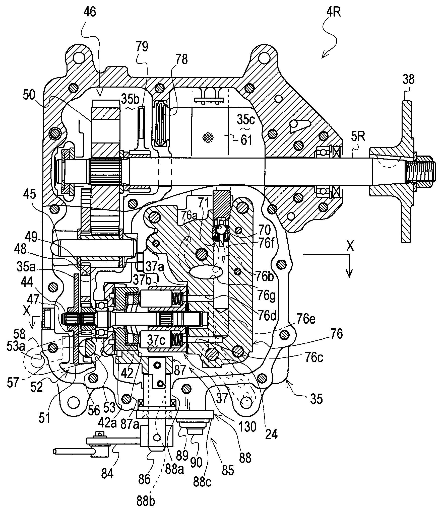
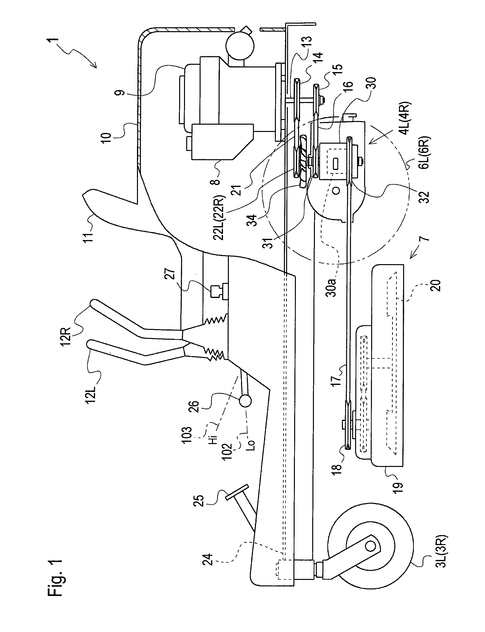
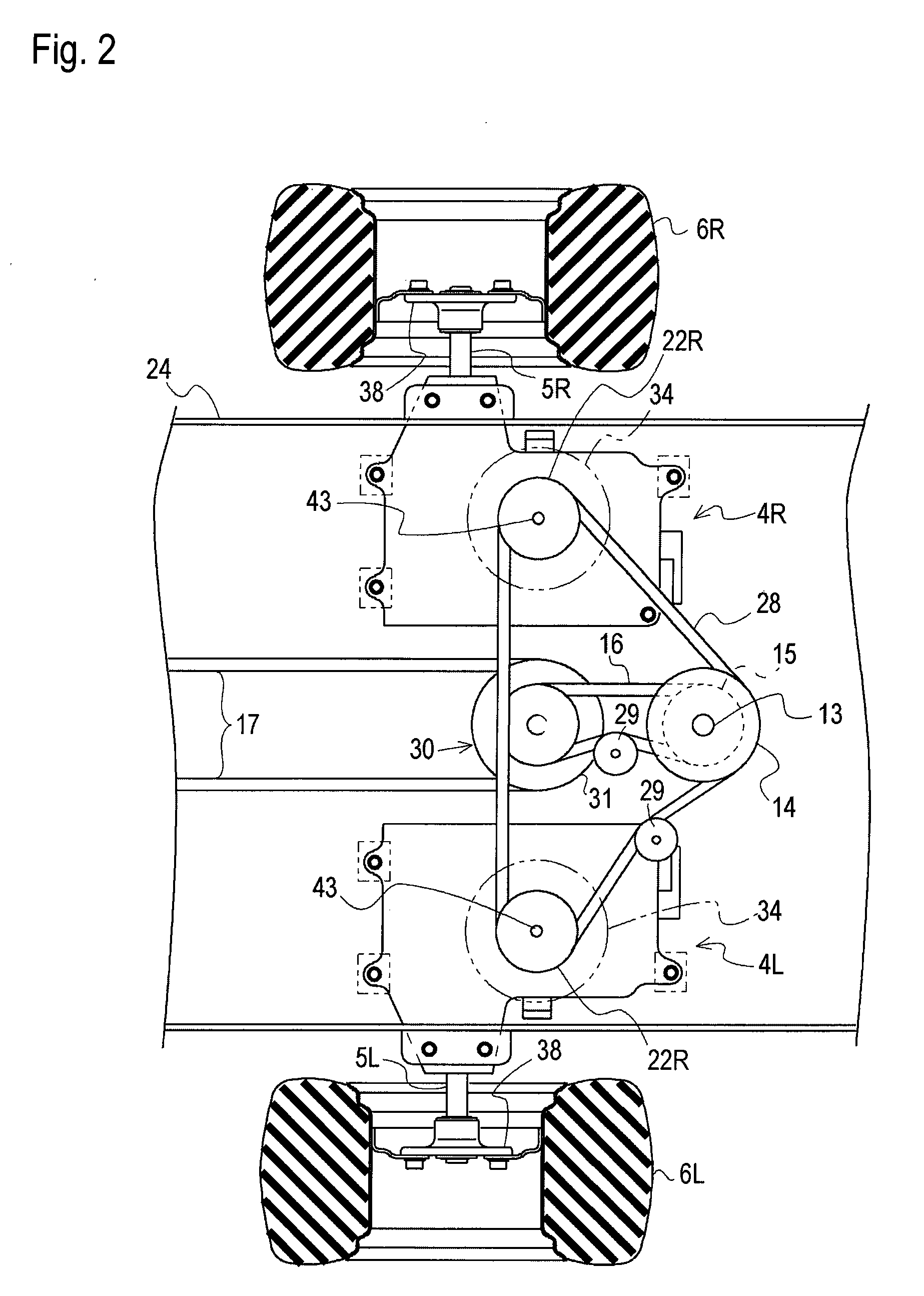
[0049]Referring to FIGS. 1, 2 and 9, description will be given of a general structure of a lawn mower serving as an embodiment of a hydraulically driven working vehicle 1 equipped with a transaxle system 2. Vehicle 1 includes a fore-and-aft extended vehicle body frame 24. Vehicle body frame 24 supports right and left front wheels (casters) 3R and 3L at right and left front portions thereof, and supports right and left transaxle units 4R and 4L constituting transaxle system 2 at right and left rear portions thereof.

[0050]Working vehicle 1 has a pair of right and left rear wheels 6R and 6L fixed on axially distal ends of respective right and left horizontal lateral axles 5R and 5L. Right transaxle unit 4R supports right axle 5R and extends right axle 5R rightwardly outward to right rear wheel 6R. Left transaxle unit 4L supports left axle 5L and extends left axle 5L leftwardly outward to left rear wheel 6L.

[0051]A mower unit 7 is disposed below a fore-and-aft intermediate portion of ve...


PUM


Abstract

A vehicle transaxle system includes a pair of right and left transaxle units equipped on a vehicle. The right transaxle unit supports a single right axle, and the left transaxle unit supports a single left axle. A variable displacement hydraulic pump is disposed in each of the right and left transaxle units so as to be driven by power from a prime mover of the vehicle. A variable displacement hydraulic motor is disposed in each of the right and left transaxle units and is fluidly connected to the corresponding hydraulic pump so as to drive the corresponding right or left axle. A movable motor displacement control member is provided in each of the transaxle unit so as to be moved to change the displacement of the corresponding hydraulic motor. An interlocking connection means is connected to both the movable motor displacement control members of the respective hydraulic motors. The vehicle is provided with a first manipulator for changing displacements of the hydraulic pumps, and is provided with a second manipulator for operating the interlocking connection means. The interlocking connection means is operated by operating the second manipulator so as to synchronously move both the movable motor displacement control members.

Description

BACKGROUND OF THE INVENTION[0001]1. Field of the Invention[0002]The present invention relates to a vehicle transaxle system for a vehicle, especially, for a working vehicle equipped with a working device, e.g., a lawn mower equipped with a mower unit, wherein the vehicle transaxle system includes right and left transaxle units each of which supports a right or left corresponding single axle.[0003]2. Related Art[0004]As disclosed in U.S. Pat. No. 6,385,971, there is a well-known conventional zero-turn type vehicle transaxle system for a working vehicle, such as a lawn mower, for enabling zero-turn of the vehicle, thereby ensuring a satisfactory working efficiency. The transaxle system includes right and left hydraulic transaxle units each of which supports a right or left corresponding single axle. Each of the transaxle units includes a hydrostatic transmission for driving the corresponding axle, and the hydrostatic transmission includes hydraulic pump and motor fluidly connected to ...

Claims


Application Information

Patent Timeline
Patent Type & Authority Applications(United States)
IPC IPC(8): F16D31/02B60K17/10F16H61/40F16H61/42F16H61/421F16H61/437
CPCA01D34/69B60Y2200/223F16H61/427B60K17/105B60K17/28
Inventor YASUDA, TOSHIFUMIIIDA, MASARUKANENOBU, HIDEKI
Owner KANZAKI KOKYUKOKI MFG
Why Eureka
Try Eureka