Fish and plant factory

Inactive Publication Date: 2009-12-10
OBRIEN & GERE ENGINEERS
1 Cites 79 Cited by

AI-Extracted Technical Summary

Problems solved by technology

One potential problem is the inevitable consumption of non-renewable fossil fuels.
A related potential problem is the potential threat to the Earth's climate.
Another problem is the high cost of energy to regulate temperatures inside the fish farm and hydroponic network.
A related problem is that conventional fish farm and hydroponic networks do not utilize the waste heat from the production of the electri...

Benefits of technology

[0012]It is another object and advantage of the present invention to use renewable energy sources instead of non-renewable energy sources in a cogeneration system set-up to create the energy to run a combined fish farm and hydroponic network, which can decrease the expense in running such a system. Cogeneration (also known as combined heat and power) refers to the combined production and utilization of electricity and heat energy, where the heat energy would normally be wasted, from a common fuel source. This “waste heat” is typically created as a byproduct during an industrial process. Instead of releasing this heat into the surrounding environment (and essentially treating this heat energy as waste heat), a cogeneration system will harness this heat energy for further uses. Cogeneration systems allow for the use of a higher percentage of energy obtained from a fuel source. This translates into fuel source conservation, and thus savings to the user of the cogeneration system, since less of the fuel needs to be used to obtain the same amount of useful energy from the fuels source (as compared to a system that does not harness the waste heat). The efficiency of a cogeneration system increases when the heat that is obtained from a fuel source is utilized close to where the heat is created and harnessed. Further, the heat energy can be in the form of hot water or steam, for example.
[0013]It is a further object and advantage of the present invention to exploit such renewable energy in a cogeneration facility, where the renewable energy could be utilized to its fullest potential thereby using less fuel and passing off the savings to the user of such a facility.
[0014]It is another object and advantage of the present invention to provide a combined fish and plant factory that can operate almost anywhere (e.g., an open lot in a city or a field in the country), and can allow food to be grown close to customers, eliminate transportation costs, enhance food safety by growing food in a controlled environment, recycles wastes, and helps conserve resources such as soil, water and wild fish populations.
[0015]In accordance with an embodiment o...

Abstract

The present invention relates to a combined interdependent fish and plant factory. An embodiment of the present invention includes a fish house connected to a greenhouse, a biofuel source, and a generator connected to the biofuel source and to at least one of the fish house and the greenhouse, where the generator is adapted to utilize biofuel as a fuel source and to provide electrical power to at least one of the fish house and the greenhouse. An embodiment can also include a waste heat recovery boiler or an algae reactor. Another embodiment includes a method for growing plants and farming fish in a combined interdependent fish and plant factory including a fish house connected to a greenhouse, including the steps of utilizing biofuel from a biofuel source to create electric power, and providing the electric power to at least one of the fish house and the greenhouse.

Application Domain

Algae productsClimate change adaptation +6

Technology Topic

Recovery boilerPlant factory +6

Image

  • Fish and plant factory
  • Fish and plant factory
  • Fish and plant factory

Examples

  • Experimental program(1)

Example

[0027]Reference will now be made in detail to the present preferred embodiments of the invention, wherein like numerals refer to like components, examples of which are illustrated in the accompanying drawings.
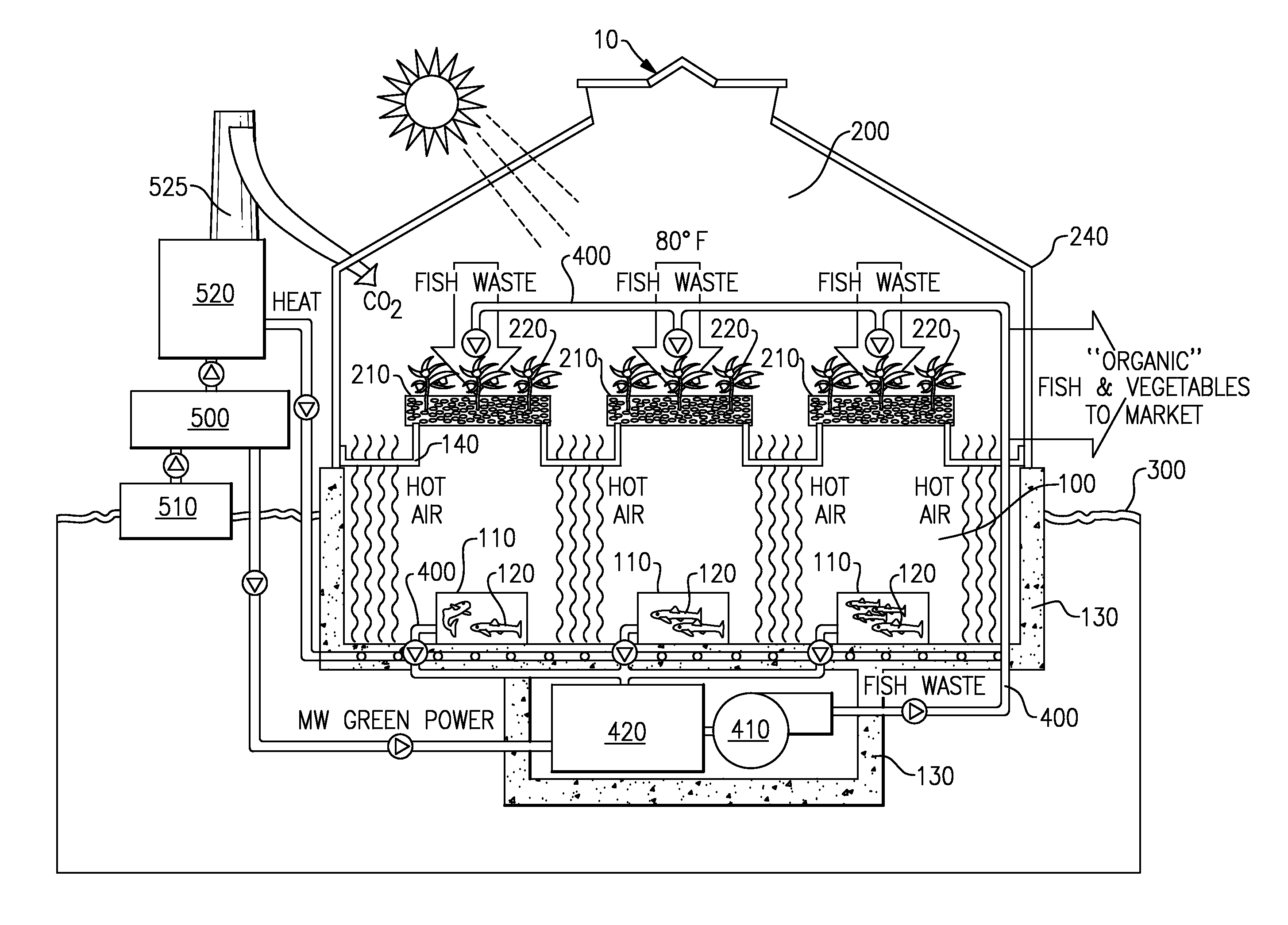
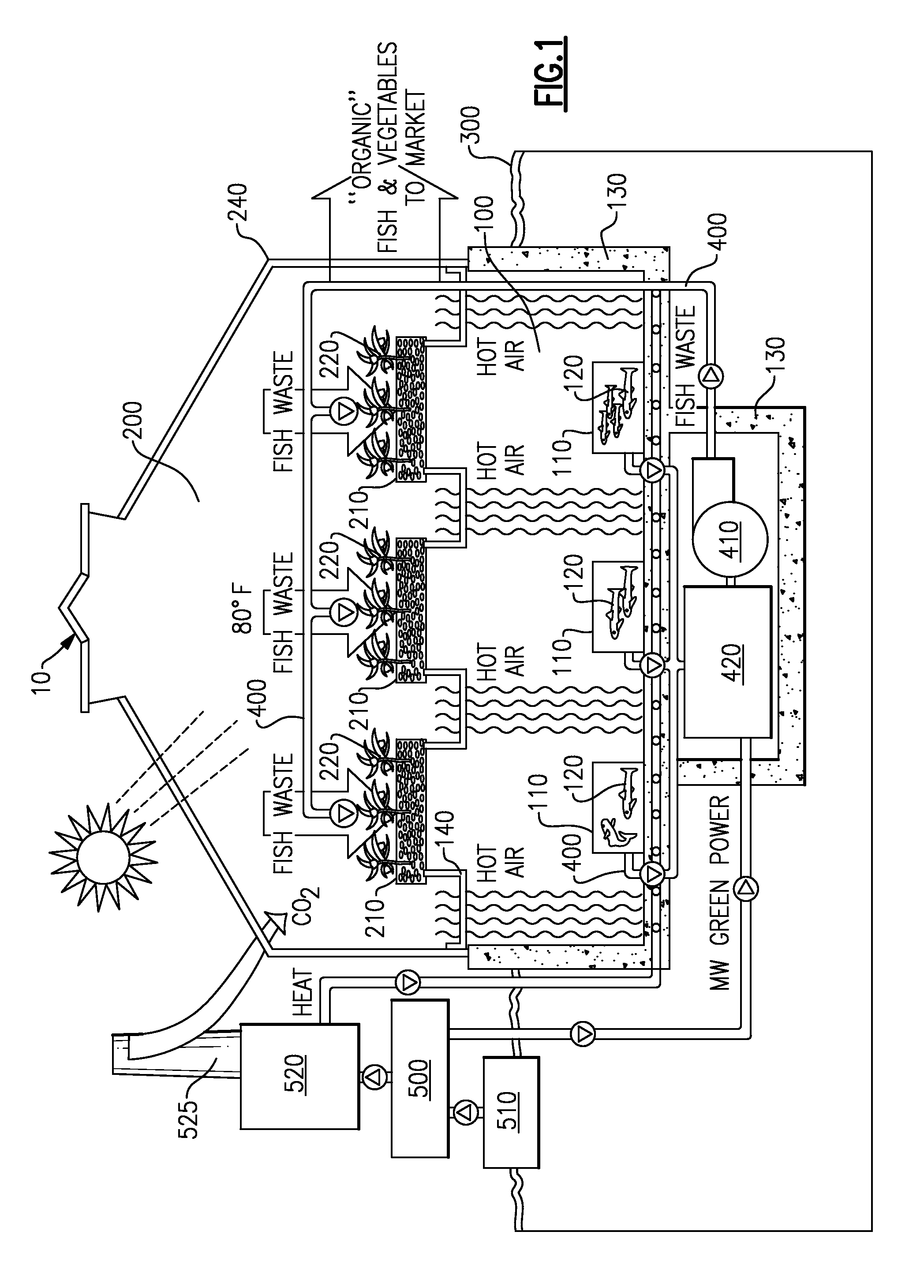
[0028]Turning to FIG. 1, a schematic view that illustrates a combined interdependent fish and plant factory 10 according to an embodiment of the present invention is shown. The combined interdependent fish and plant factory 10 comprises a fish house 100 with a plurality of fish tanks 110 adapted for containing water and fish 120 therein, and a greenhouse 200 with a plurality of hydroponic tanks 210 adapted for containing plants 220 in grow beds (not shown) therein, within a multilevel housing unit.
[0029]The fish house 100 is located underneath the greenhouse 200 and with the tanks 110 substantially below the ground 300. The fish house 100 is surrounded on three sides by a concrete slab foundation 130, and is preferably adapted for excluding sunlight and maintaining a relatively constant temperature for the fish tanks 110 (e.g., approximately 80-85° F.), and the air surrounding the fish tanks (e.g., approximately 85-90° F.).
[0030]The hydroponic tanks 210 are located in the greenhouse 200 which is positioned above the fish house 100. The separation boundary between the greenhouse 200 and the fish house 100 is surface 140 (which serves as the ceiling of the fish house 100 and the floor of the greenhouse 200). The remaining walls of the greenhouse 240 may be constructed of conventional greenhouse transparent or translucent material, such as glass, plexiglass or plastic sheeting.
[0031]A pipe system 400, which ultimately connect the hydroponic tanks 210 of the greenhouse 200 with the fish tanks 110 of the fish house 100 for the purpose of circulating the fish tank water with fish waste through the hydroponic tanks with the assistance of at least one pump 410, is also shown in FIG. 1. The fish tank water with the fish waste is pumped from the fish tanks through the pipe system 400, through at least one biofilter 420, and then to the hydroponic tanks 210 where the fish waste is removed from the water and utilized by the plants 220 as a source of nutrients. After the fish waste is removed, the water is circulated back to the fish tanks 110 where the cycle begins again. In the embodiment shown in FIG. 1, the biofilter 420 and the pump 410 are shown within an extension of the concrete slab foundation 130, which is underneath the fish house 100.
[0032]Generators 500 can run on natural gas and any secondary fuel (see FIG. 2) including any conventional liquid biofuel, as noted supra. As shown in FIG. 1, the generator 500 is connected to a source of biofuel 510 and a waste heat recovery boiler 520 with an exhaust stack 525. The generator 500 utilizes biofuel from the biofuel source to provide MW (e.g., 1.75) of electrical power (i.e., green power—power created from a renewable energy source) to the combined interdependent fish and plant factory 10 to, e.g., run the filter 420 and the pumps 410. The waste heat recovery boiler 520 which harnesses the waste heat from the generator 500, provides this waste heat energy in the form of steam and/or hot water to the combined interdependent fish and plant factory 10 for optimum growth/yield of the fish 120 and plants 220 within the factory 10. For example, the waste heat energy is provided to the floor of the concrete slab 130 of the fish house 100, as shown in FIG. 1. The heat energy, in the form of hot air, is shown rising from the floor of the concrete slab 130 of the fish house 100, through the fish house 100, and to the greenhouse 200. CO2 created during the combustion of these biofuels is also harnessed from the exhaust stacks 525 and provided to the combined interdependent fish and plant factory 10 for purposes such as photosynthesis and optimum plant growth/yield.
[0033]Turning to FIG. 2, a schematic view that illustrates a combined interdependent fish and plant factory 10 according to an additional embodiment of the present invention is shown. Similarly to FIG. 1, FIG. 2 shows a combined interdependent fish and plant factory 10 which comprises a fish house 100 with a plurality of fish tanks 110 adapted for containing water and fish 120 therein, and a greenhouse 200 with a plurality of hydroponic tanks 210 adapted for containing plants 220 in grow beds (not shown) therein, within a multilevel housing unit. FIG. 2 also shows, however, an algae reactor 600, adjacent to the greenhouse 200 on the “first floor,” as part of the combined interdependent fish and plant factory 10.
[0034]A generator 500, which can run on natural gas and any secondary fuel, as described supra, is also shown in FIG. 2. The generator 500 is connected to a waste heat recovery boiler 520, which is connected to exhaust stacks 525. The generator 500 can provide MW (e.g., 1-2 MW) of electric (green) power to the combined interdependent fish and plant factory 10, as well as to a substation and a power grid to power other facilities A, such as a college campus, shopping mall, business park, county, city, or town and the like. The waste heat recovery boiler 520 provides waste heat energy in the form hot water/steam to the concrete slab 130 of the fish house 100. Waste heat energy in the form of hot air rises from the fish house in the “basement” to the greenhouse 200 and to the algae reactor 600. Waste heat energy in the form hot water/steam may also be provided to other facilities B, such as a college campus, shopping mall, business park, county, city, or town and the like.
[0035]A biodiesel refinery 550 (a biofuel source) is provided and is connected to a supplemental burner 560 for electric power production, which is also connected to the waste heat recovery boiler 520. This biodiesel refinery 550 can process biodiesel from sources such as vegetable or waste cooking oil, soy oil, algae oil, or fish waste, and the like (which can be used as a fuel source by the generator 500, as discussed supra). Algae oil from the algae reactor 600 may be provided as a source of biodiesel to the biodiesel refinery 550, and fish waste from the fish tanks 110 of the fish house 100 may also be provided as a source of biodiesel to the biodiesel refinery 550.
[0036]Turning to FIG. 3, a schematic view that illustrates a combined interdependent fish and plant factory 10 according to an additional embodiment of the present invention is shown. Similarly to FIGS. 1 and 2, FIG. 3 shows a combined interdependent fish and plant factory 10 which comprises a fish house 100 with fish tanks 110 adapted for containing water and fish 120 therein, and a greenhouse 200 with a plurality of hydroponic tanks 210 adapted for containing plants 220 in grow beds (not shown) therein, within a multilevel housing unit. FIG. 3 also shows an algae reactor 600 as part of the combined interdependent fish and plant factory 10.
[0037]A generator 500, which can run on natural gas and any secondary fuel (fuel made from plat or animal sources such as wood, or biodiesel made from fish guts or algae), is also shown in FIG. 3. The generator 500 is connected to a waste heat recovery boiler 520, which is connected to exhaust stacks 525. CO2 emitted by the boiler through the exhaust stack 525 can enter the greenhouse 200 to enhance the growth of hydroponically grown vegetables (such as tomatoes, peppers, and/or broccoli), and can enter the algae reactor 600 to help grow algae. The generator 500 can provide electric (green) power to the combined interdependent fish and plant factory 10, as well as to a substation and a power grid to power other facilities, such as a college campus, shopping mall, business park, county, city, or town and the like. The waste heat recovery boiler 520 provides waste heat energy in the form hot water/steam to the fish house 100, greenhouse 200 and algae reactor 600. Waste heat energy in the form hot water/steam may also be provided to other facilities, such as a college campus, shopping mall, business park, county, city, or town and the like.
[0038]A biodiesel refinery 550 (a biofuel source) is provided and is connected to a supplemental burner 560 for electric power production, which is also connected to the waste heat recovery boiler 520. This biodiesel refinery 550 can process biodiesel from sources such as algae oil from the algae reactor 600, which can be used as a fuel by the reactor 500. Leftover algae cakes can be used as fish food for the fish 120 in the fish tanks 110.
[0039]While the invention is susceptible to various modifications, and alternative forms, specific examples thereof have been shown in the drawings and are herein described in detail. It should be understood, however, that the invention is not to be limited to the particular forms or methods disclosed, but to the contrary, the invention is to cover all modifications, equivalents and alternatives falling within the spirit and scope of the claimed invention.

PUM

no PUM

Description & Claims & Application Information

We can also present the details of the Description, Claims and Application information to help users get a comprehensive understanding of the technical details of the patent, such as background art, summary of invention, brief description of drawings, description of embodiments, and other original content. On the other hand, users can also determine the specific scope of protection of the technology through the list of claims; as well as understand the changes in the life cycle of the technology with the presentation of the patent timeline. Login to view more.

Similar technology patents

Classification and recommendation of technical efficacy words

Why Eureka
Try Eureka