Fuel metering valve assembly including thermal compensation mechanism

a technology of thermal compensation mechanism and fuel metering valve, which is applied in the direction of functional valve types, turbine/propulsion fuel valves, machines/engines, etc., can solve the problems of system limitation in certain respects, system not providing consistent mass flow rate to engine combustors over the operative temperature range, and unfavorable maintenance and repair. , to achieve the effect of increasing the width of the displacement gap

Inactive Publication Date: 2009-12-10
HONEYWELL INT INC
View PDF6 Cites 48 Cited by
  • Summary
  • Abstract
  • Description
  • Claims
  • Application Information

AI Technical Summary

Benefits of technology

[0007]A fuel delivery and control system is also provided for supplying a metered amount of fuel to an aircraft engine combustor having an engine controller associated therewith. The fuel delivery and control system includes a fuel source and a metering valve fluidly coupled between the fuel source and the aircraft engine combustor. The metering valve includes a valve housing having a flow passage therethrough, and a valve element movably mounted within the valve housing. A position sensor is coupled to the valve element and separated therefrom by a displacement gap. The position sensor is also coupled to the engine controller and configured to relate thereto the sensed position of the valve element. A valve actuator is coupled to the valve element and to the engine controller. The valve actuator is configured to adjust the position of the valve element in accordance with command signals received from the engine controller. A thermal compensation mechanism is coupled between the valve element and the position sensor. The thermal compensation mechanism is configured to increase the width of the displacement gap as the fuel's temperature increases over an operative temperature range.

Problems solved by technology

If the fuel delivery and control system does not account for this change in fuel density, the system might not provide a consistent mass flow rate to the engine combustors over the operative temperature range.
Although fuel delivery and control systems of the type described above are generally effective at regulating mass flow rate over an operative temperature range, such systems are limited in certain respects.
For example, to achieve sufficient displacement of the bypass valve spring, an undesirably large number of bi-metallic discs may be needed.

Method used


Image

  • Fuel metering valve assembly including thermal compensation mechanism
  • Fuel metering valve assembly including thermal compensation mechanism
  • Fuel metering valve assembly including thermal compensation mechanism

Examples


Embodiment Construction

[0014]The following detailed description is merely exemplary in nature and is not intended to limit the invention or the application and uses of the invention. Furthermore, there is no intention to be bound by any theory presented in the preceding background or the following detailed description.

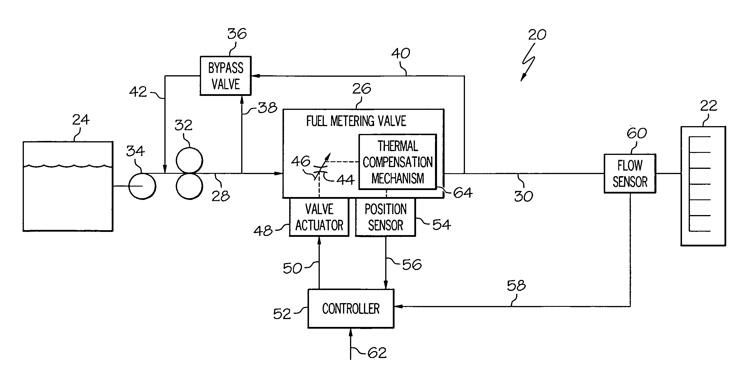
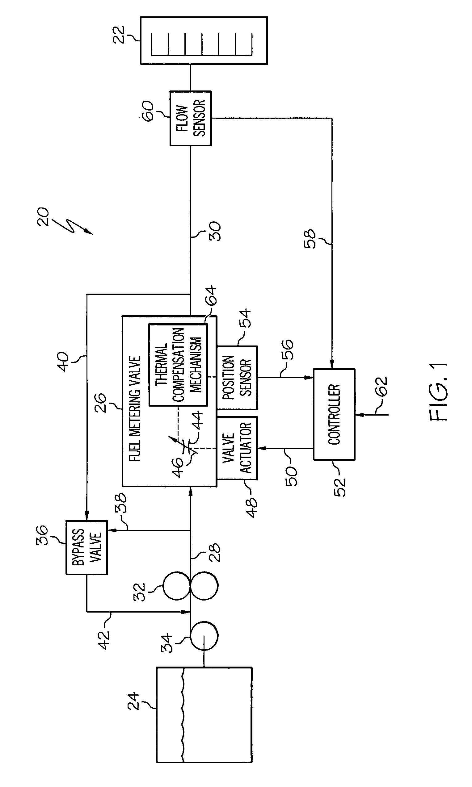
[0015]FIG. 1 is a simplified schematic diagram of an exemplary fuel delivery and control system 20 suitable for supplying a metered amount of fuel to at least one combustor 22 (or other such fuel load) associated with an aircraft's gas turbine engine. Fuel delivery and control system 20 is shown in FIG. 1 and will be described below as including only certain components useful for descriptive purposes; however, it will be understood that, in actual practice, system 20 may include additional or alternative components that are conventional in the field and not shown in FIG. 1 for clarity. Furthermore, although described in the context of an aircraft fuel delivery and control system, it should b...


PUM


Abstract

A metering valve assembly is provided for metering a fluid. The metering valve assembly includes a position sensor, metering valve, and a thermal compensation mechanism. The metering valve includes a valve housing having a flow passage therethrough, and a valve element movably mounted within the valve housing. The thermal compensation mechanism is coupled between the position sensor and the valve element and configured to adjust the displacement of the position sensor relative to the valve element as a function of fluid temperature.

Description

TECHNICAL FIELD[0001]The present invention relates generally to an aircraft fuel delivery and control system and, more particularly, to a fuel metering valve assembly including a thermal compensation mechanism configured to compensate for changes in fuel density.BACKGROUND[0002]Fuel delivery and control systems are deployed on aircraft to supply metered amounts of fuel to combustors associated with the aircraft's gas turbine engines. In a generalized fuel delivery and control system, a metering valve is fluidly coupled between a fuel source (e.g., one or more storage tanks) and the engine combustors. The metering valve includes a valve element (e.g., a piston) that is slidably mounted within a valve housing (e.g., a sleeve). The valve element is movable between an open position, a closed position, and various intermediate positions. The position of the valve element is adjusted by a valve actuator, which is, in turn, controlled by an engine controller. During operation of the fuel d...

Claims


Application Information

Patent Timeline
Patent Type & Authority Applications(United States)
IPC IPC(8): F16K17/38
CPCY02T50/671F02C7/232Y10T137/8242Y10T137/7737Y02T50/60
Inventor ARNETT, ERIC M.
Owner HONEYWELL INT INC
Why Eureka
Try Eureka