
Ultrafine pattern discrimination using transmitted/reflected workpiece images for use in lithography inspection system

a technology of lithography and workpieces, applied in the field of workpiece pattern detection and inspection technologies, can solve the problems of extremely small size of pattern defects to be detected by inspection, and reduce yield, so as to achieve the effect of optimizing inspection sensitivity

Active Publication Date: 2009-12-10
KIOXIA CORP +1
View PDF7 Cites 9 Cited by
  • Summary
  • Abstract
  • Description
  • Claims
  • Application Information

AI Technical Summary

Benefits of technology

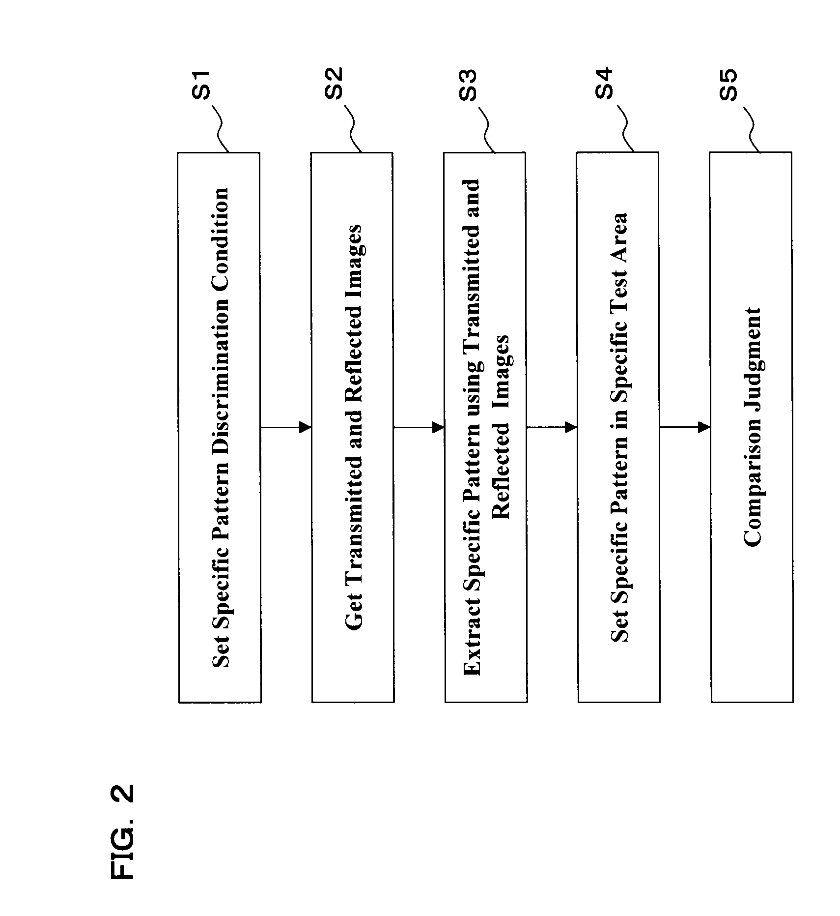
[0006]It is therefore an object of the present invention to provide a technique for discriminating a specific pattern from the pattern of a workpiece under inspection, by using both a transmissive image and a reflective image of the workpiece pattern. Another object of this invention is to optimize the inspection sensitivity with respect to a specific pattern of the workpiece being tested. A further object of the invention is to provide a method and apparatus capable of performing accurate pattern inspection by discriminating an assist pattern from among various pattern components on a workpiece being tested.
[0011]According to the invention as disclosed herein, it is possible to discriminate a specific pattern(s) from among pattern shapes of a workpiece under inspection, by using transmissive and reflective images of the workpiece. It is also possible to optimize the inspection sensitivity relative to the specific pattern of the workpiece. In addition, it is possible to precisely perform the intended pattern inspection by discrimination of one or more assist patterns of the workpiece.

Problems solved by technology

One of major causes for such yield reduction is the presence of defects of a photomask, which is used for exposure and transfer of an ultrafine circuit pattern onto semiconductor wafers by photolithography processes.
Notably, with the growth in miniaturization of on-wafer ULSI circuitry, pattern defects have become extremely smaller in size to be detected by inspection.

Method used


Image

  • Ultrafine pattern discrimination using transmitted/reflected workpiece images for use in lithography inspection system
  • Ultrafine pattern discrimination using transmitted/reflected workpiece images for use in lithography inspection system
  • Ultrafine pattern discrimination using transmitted/reflected workpiece images for use in lithography inspection system

Examples


Embodiment Construction

[0023]Currently preferred embodiments of this invention will be described with reference to the accompanying figures of the drawing below.

Workpiece Pattern Discrimination Device

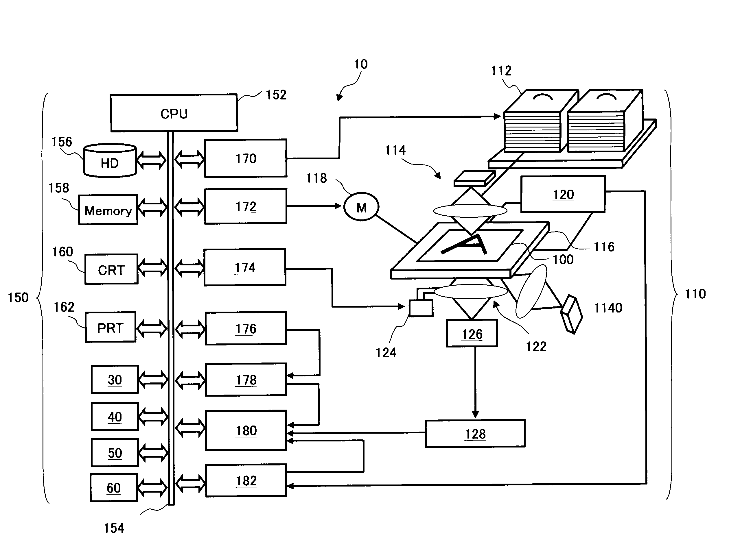
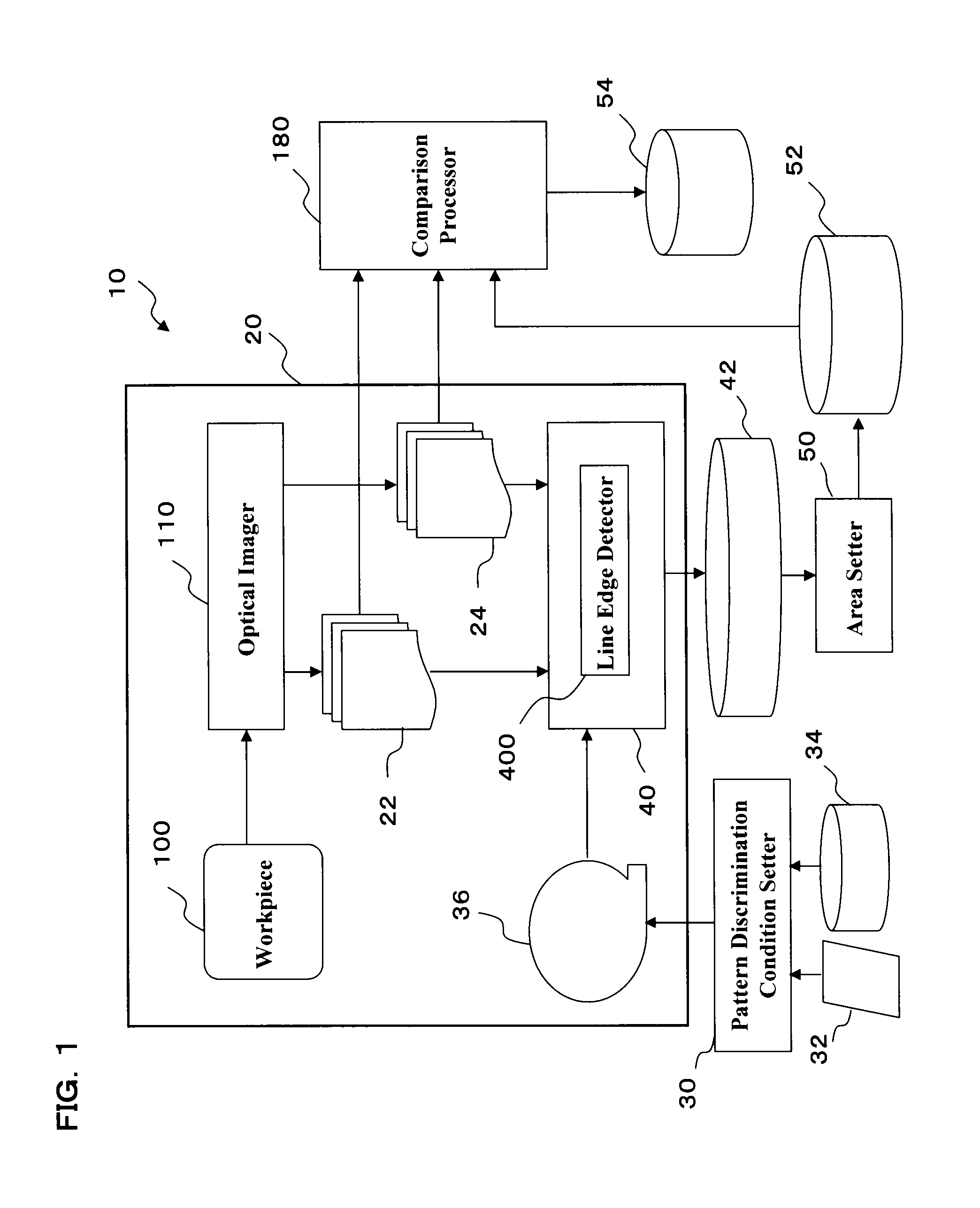
[0024]Referring to FIG. 1, a workpiece inspection apparatus 10 is shown, which employs a pattern discrimination device 20 in accordance with one embodiment of the invention. The pattern discriminator device 20 includes an optical image acquisition unit 110, which operates to acquire or “capture” two different kinds of optical images—i.e., an image 22 of transmitted light and an image 24 of reflected light—from a highly integrated circuit pattern of a workpiece under inspection. The workpiece may be a photomask, semiconductor wafer, LCD substrate or else. The pattern discriminator 20 also includes a specific pattern detection unit 40, which uses the transmitted image 22 and reflected image 24 along with a specific pattern distinguishing / identifying condition 36 to detect for extraction a specific or “particula...


PUM


Abstract

A technique for discriminating a specific pattern, such as an assist pattern, from an integrate circuit pattern of a workpiece by using transmission and reflection images of the workpiece pattern is disclosed. A pattern discrimination device includes an optical image acquisition unit for acquiring a transmissive image of a workpiece having a pattern and a reflective image of the workpiece pattern simultaneously, and a specific pattern detection unit which detects for extraction a specific pattern from among pattern shapes of the transmissive and reflective images in conformity with a distinguishing condition of the specific pattern. A workpiece pattern inspection apparatus using the device is also disclosed.

Description

CROSS-REFERENCE TO RELATED APPLICATIONS[0001]Priority is claimed to Japanese Patent Application (JPA) No. 2008-148889, filed Jun. 6, 2008, and to JPA No. 2008-150072, filed Jun. 9, 2008, the contents of which are incorporated herein by reference.TECHNICAL FIELD[0002]The present invention relates generally to workpiece pattern detection and inspection technologies and, more particularly, to a technique for discriminating and inspecting patterns of workpieces including, but not limited to, photo-masks, wafers or substrates to be used in the process of fabricating semiconductor devices or liquid crystal display (LCD) panels. This invention also relates to workpiece inspection systems using the pattern discrimination / inspection technique.DESCRIPTION OF RELATED ART[0003]Recent advances in ultralarge-scale integration (ULSI) technology result in feature length and related dimensions of circuit patterns decreasing from the order of submicrons to nanometers. As ULSI circuit patterns shrink ...

Claims


Application Information

Patent Timeline
Patent Type & Authority Applications(United States)
IPC IPC(8): G06K9/62G06K9/00
CPCG01N21/95607G01N2021/95676G06T2207/30148G06T7/001G06T7/0083G02F1/1309G06T7/12
Inventor HARABE, NOBUYUKI
Owner KIOXIA CORP
Learn More