
Vehicular lamp

a technology of vehicle lamps and lampshades, which is applied in the field of vehicle lamps, can solve the problems of easy fluctuation of lens characteristics and inability to avoid deterioration of transmittance, and achieve the effect of reducing color separation and reducing the degree of color separation

Active Publication Date: 2009-12-17
NALUX CO LTD
View PDF4 Cites 8 Cited by
  • Summary
  • Abstract
  • Description
  • Claims
  • Application Information

AI Technical Summary

Benefits of technology

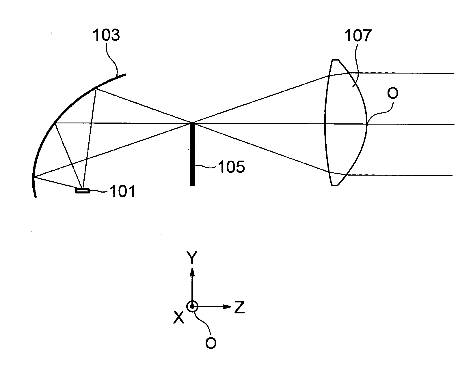
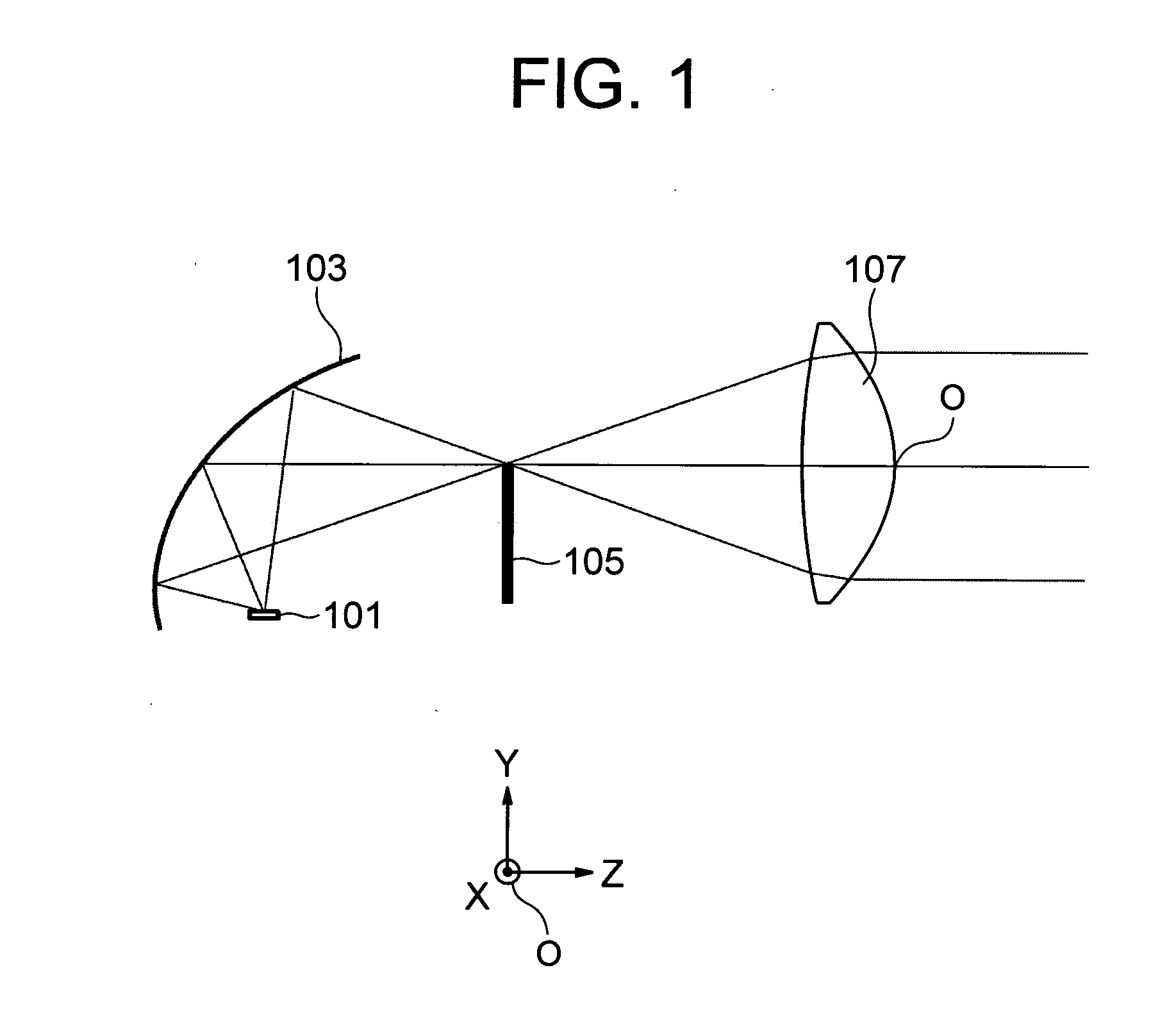
The invention is about a vehicular lamp that reduces color separation and maintains optical characteristics, while considering the characteristics of the light source. The lamp includes a light source, reflector, shade, and projector lens. A diffraction grating is placed in the projector lens to reduce color separation. The position of the grating and the focal distance of the lens are determined based on the color temperature of the light source. This helps to control the color separation and reduce it to a minimum. The invention also eliminates the need for a reflector and shade, making the lamp more compact.

Problems solved by technology

This is a common problem irrespective of a type of the light source.
In the method disclosed in JP-A No. 8-17045, because a luminous intensity pattern is smudged by utilizing a light scattering effect of the texturing performed to the whole of the lens surface, unfortunately deterioration of transmittance cannot be avoided and a lens characteristic is easily fluctuated according to a feature of the texturing.

Method used


Image

  • Vehicular lamp
  • Vehicular lamp
  • Vehicular lamp

Examples


embodiment b

[0137]FIG. 17 illustrates a configuration of a vehicular lamp according to Embodiment B. In Embodiment B, the light passing through a projector lens 107B is not collected.

[0138]In Embodiment B, the correlated color temperature of the light source ranges from 3200 K to 6500 K. Hereinafter the light source whose correlated color temperature ranges from 3200 K to 6500 K is referred to as intermediate-temperature light source. In Embodiment B, the following expression holds:

0.28fD / f / Abbe<0.36

That is, the focal position B to the blue light of the portion in which the diffraction surface of the projector lens 107B is provided is substantially matched with the focal position R to the red light of the portion by adjusting the power of the diffraction surface. A position of a shade 105B on the optical axis is located closer to the projector lens 107B than the focal position closest to the projector lens 107B in the focal positions to the light having the wavelength of 450 nm to 700 nm. In Em...

embodiment c

[0139]FIG. 18 illustrates a configuration of a vehicular lamp according to Embodiment C. In Embodiment C, the light passing through a projector lens 107C is not collected.

[0140]In Embodiment C, the correlated color temperature of the light source is higher than 6500 K. Hereinafter the light source whose correlated color temperature is higher than 6500 K is referred to as high-temperature light source. In Embodiment C, the following expression holds:

0.33fD / f / Abbe

That is, the focal position R to the red light of the portion in which the diffraction surface of the projector lens 107C is provided is located on the light source side of the focal position B to the blue light of the portion by relatively weakening the power of the diffraction surface. A position of a shade 105C on the optical axis is located closer to the projector lens 107C than the focal position closest to the projector lens 107C in the focal positions to the lights having the wavelength of 450 nm to 700 nm. In Embodime...

embodiment d

[0141]FIG. 19 illustrates a configuration of a vehicular lamp according to Embodiment A. In Embodiment D, the light passing through a projector lens 107D is collected.

[0142]In Embodiment D, the light source is the low-temperature light source. In Embodiment D, the following expression holds:

0.34fD / f / Abbe

[0143]That is, the focal position R to the red light of the portion in which the diffraction surface of the projector lens 107D is provided is located on the light source side of the focal position B to the blue light of the portion by relatively weakening the power of the diffraction surface. A position of a shade 105D on the optical axis is kept farther away from the projector lens 107D than the focal position farthest away from the projector lens 107D in the focal positions to the lights having the wavelength of 450 nm to 700 nm. In Embodiment D, the blue ray is generated in the circumferential portion of the light flux with which the object ahead is irradiated through the project...


PUM


Abstract

A vehicular lamp includes a light source, a reflector, a shade, and the projector lens. Light emitted from the light source is reflected by the reflector, and the light is partially blocked by the shade. Light which is not blocked is transmitted through the projector lens, and an object ahead of a vehicle is irradiated with the light. A diffraction grating is provided in a region including an end portion of a light passing region of at least one surface in the projector lens in order to reduce color separation. Magnitude of fD / f / Abbe and a position of the shade on an optical axis are determined according to a correlated color temperature of the light source so as to reduce the color separation caused by a characteristic of the light source. f is a focal distance of the projector lens, with the focal distance of the projector lens being determined by a marginal ray passing through the end portion. fD is a focal distance caused by a grating pitch of a diffraction surface, with the focal distance caused by the grating pitch being determined by the marginal ray passing through the end portion. Abbe is an Abbe number.

Description

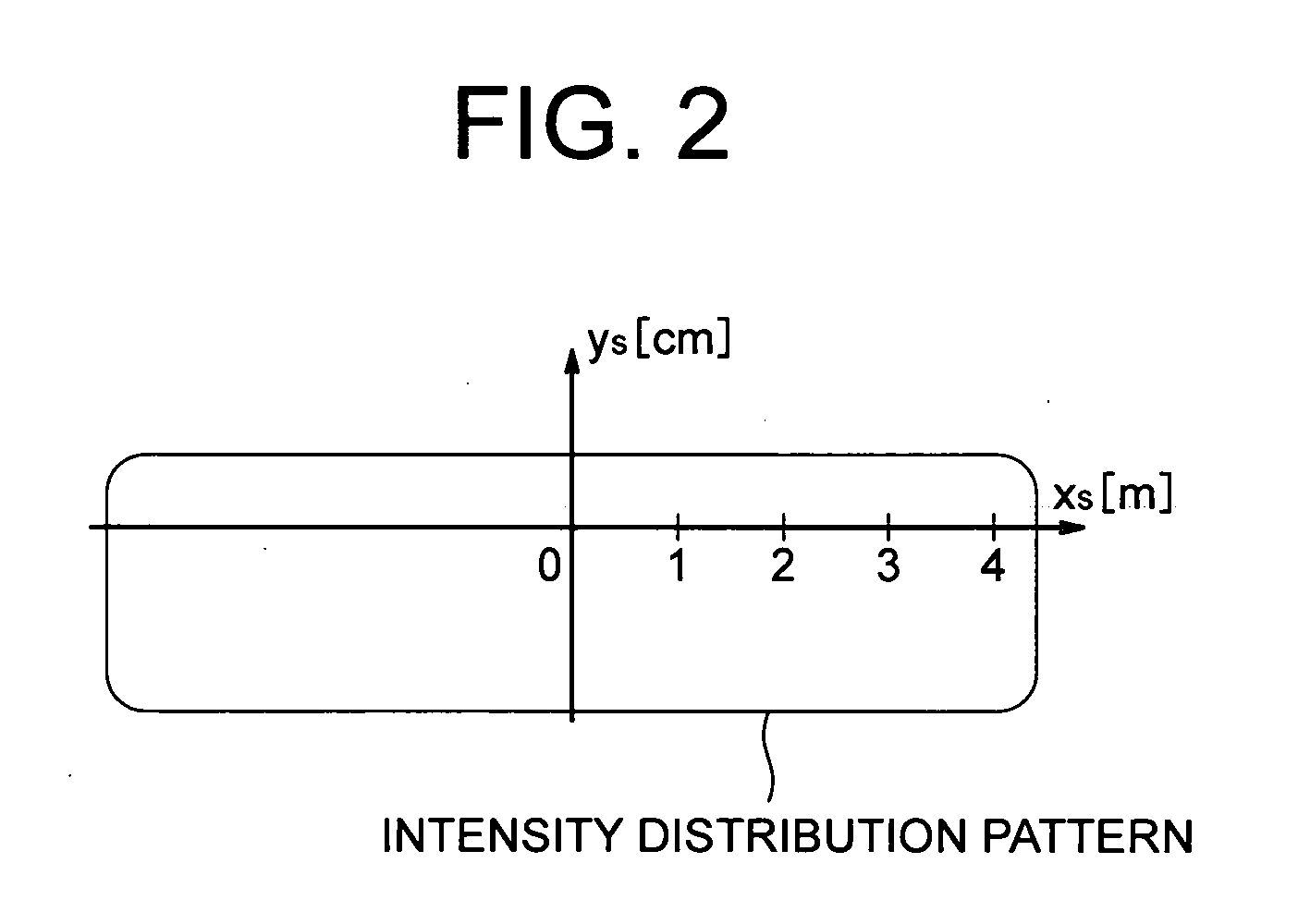
BACKGROUND OF THE INVENTION[0001]1. Field of the Invention[0002]The present invention relates to a vehicular lamp.[0003]2. Background Art[0004]An HID lamp (High Intensity Discharge lamp), a halogen lamp, an LED (Light Emitting Diode), and the like are used as a light source of the vehicular lamp (such as a headlamp). In an optical system of a projection-type vehicular lamp, light emitted from the light source is reflected by a reflector, the light passes through a shade so as to form a cut-off line, and an object ahead a vehicle is irradiated with the light transmitted through a projector lens. In any light source, the light transmitted through the projector lens generates color separation derived from color aberration of the projector lens near an edge of a light distribution pattern. This is a common problem irrespective of a type of the light source.[0005]A white LED that is of the light source has a strong spectrum in a specific wavelength region like an LED (a blue LED and a ye...

Claims


Application Information

Patent Timeline
Patent Type & Authority Applications(United States)
IPC IPC(8): B60Q1/00
CPCF21S48/1159F21S48/1258F21V5/002G02B5/1814G02B27/4288G02B27/0911G02B27/0927G02B27/425G02B27/0037F21S41/148F21S41/255
Inventor KANAI, NORIFUMI
Owner NALUX CO LTD
Learn More