
Amplitude modulated pulse transmitter

Active Publication Date: 2009-12-17
BARE JAMES E
View PDF5 Cites 11 Cited by
  • Summary
  • Abstract
  • Description
  • Claims
  • Application Information

AI Technical Summary

Benefits of technology

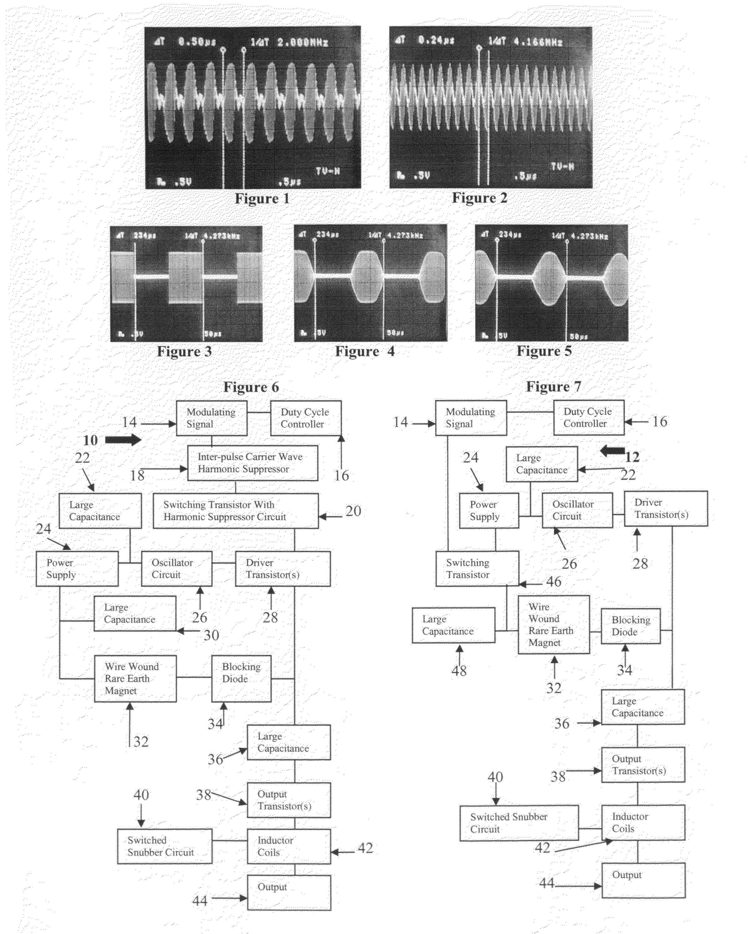
[0012]At times it may be necessary for a generated pulse to be shorter than a certain time duration, for example 1 microsecond. Nanosecond time duration pulses have uses in data transmission, radar, and with cellular biological process manipulation. An ideally shaped 500 KHz pulse at 50% duty cycle will have a duration of 1 microsecond. Adjustment of the duty cycle is capable of significantly shortening the pulse time duration. By using a duty cycle of 25%, a 500 KHz pulse will have a time duration of 500 nano seconds. At a modulation frequency of 5.5 MHz, and 25% duty cycle, a measured pulse can be generated of 100 ns.

Problems solved by technology

The majority of AM pulse transmitters are not designed for variable MHz frequency bandwidth modulation.
A variable pulse rate amplitude modulated transmitter of wide modulation bandwidth is subject to several attributes which are difficult to design.
As pulse frequencies, or pulse bandwidth increases, circuit reactance increase, causing significantly diminished output power levels.
Increased reactance that occurs with large increases in modulation frequency can cause an imbalance of the output impedance value.
Large swings in circuit reactance cause unstable output impedances.

Method used


Image

  • Amplitude modulated pulse transmitter
  • Amplitude modulated pulse transmitter
  • Amplitude modulated pulse transmitter

Examples


second embodiment

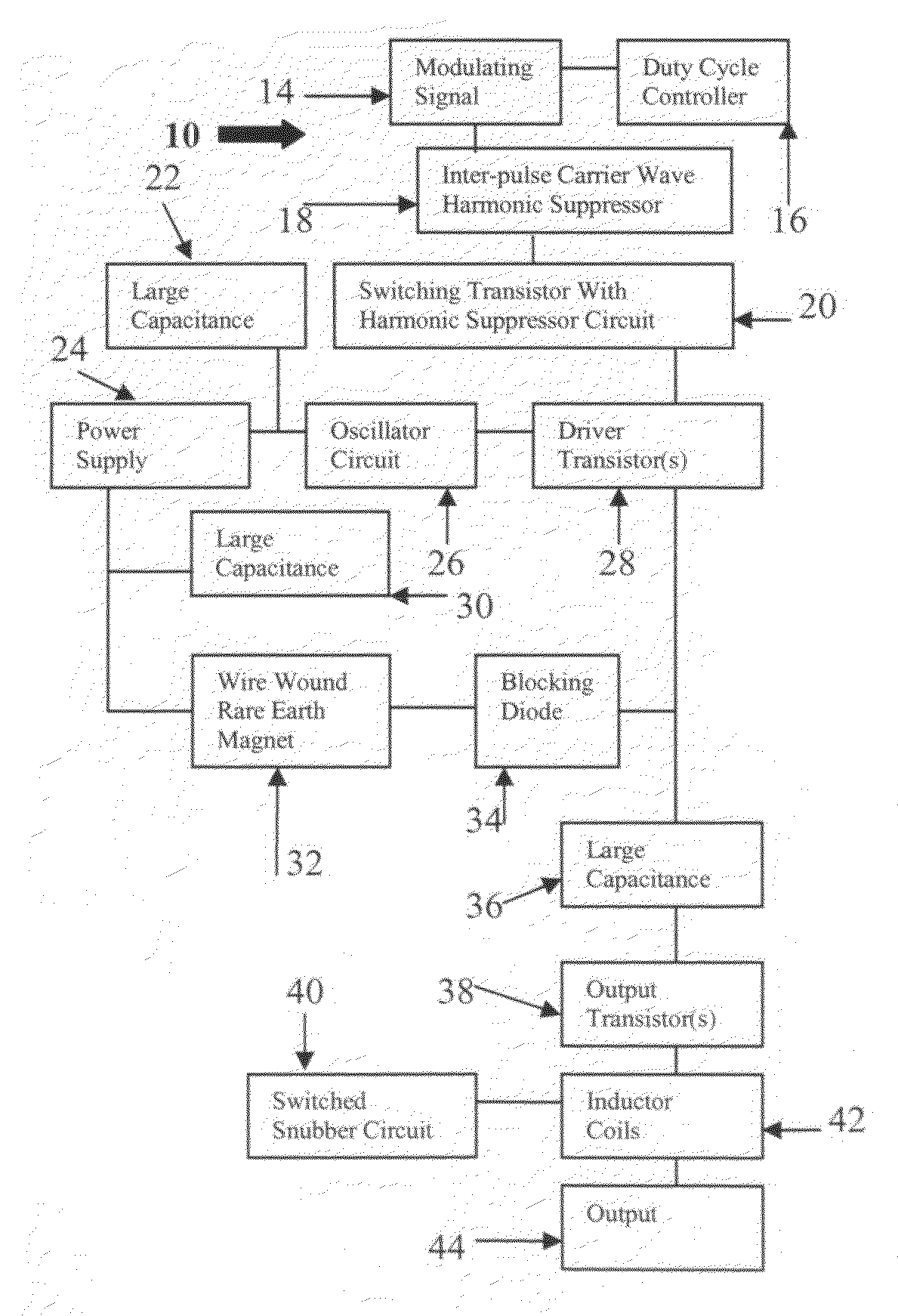
[0034]The pulse shaped, frequency response and irregularity of each carrier oscillation in the pulse is corrected by stabilizing the pulse shape at high frequencies. This is accomplished utilizing the large capacitors 22, 30 and 36 of FIG. 6 as well as the large capacitors 22, 36 and 48 of the circuit illustrated with respect to FIG. 7. It has been found that electrolytic capacitors having a range of 3300 uf to approximately 10,000 uf are added to improve the pulse shape and frequency response. The capacitor 22 in both circuits is provided in parallel to the low voltage input 24 of the power supply that powers an oscillator circuit 26. A second large electrolytic capacitor 30 having the same parameters of the capacitor 22 is provided in parallel to the high voltage input side of the circuit between the power supply 24 and the rare earth magnet 32. The large capacitor 48 of FIG. 7 is provided between the power supply 24 and the rare earth magnet 32 through a switching transistor 46. ...

first embodiment

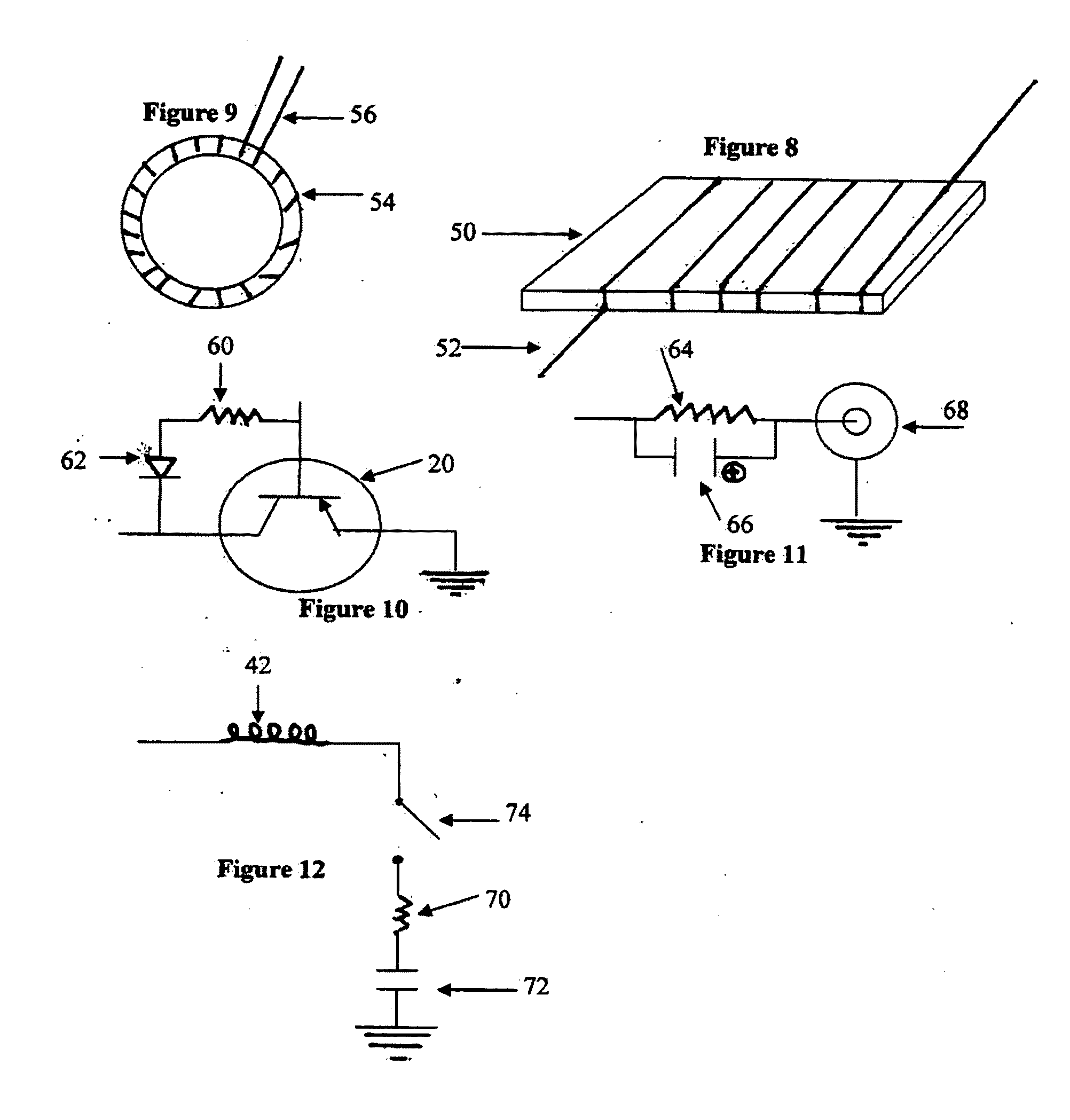
[0040]Circuit ringing between pulses can become evident at modulation frequencies of 1 MHz and above. This is important since the range of the transmitter of the present invention can be as great as 4 MHz and above. If severe enough, the circuit ringing can cause limitation of the pulse bandwidth capability. One manner in which this situation can be alleviated would be to utilize a harmonic suppressor 18 with a switching transistor 20 in the first embodiment illustrated with respect to FIG. 6. This switching transistor along with the harmonic suppressor circuit is illustrated in FIG. 10. The switching transistor 20 is utilized with a resistor 60 and a diode 62. The resistor is approximately 12 ohms and one end is connected to the base of the switching transistor 20. The other end of the resistor 60 is attached to the anode of the diode 62. The cathode of the diode is connected to the collector of the switching transistor 20.

[0041]Another manner of controlling the circuit ringing is ...


PUM


Abstract

An amplitude modulated pulse transmitter designed to operate across a multi MHz range of modulation frequencies. A wire wound rare earth magnet is to be utilized instead of the typical modulation transformer. Additionally, a plurality of electrolytic capacitors are also employed in the transmitter.

Description

CROSS-REFERENCE TO RELATED APPLICATION[0001]The present patent application claims the priority of U.S. provisional patent application Ser. No. 61 / 129,243, filed on Jun. 13, 2008, and incorporates the material therein by reference.FIELD OF THE INVENTION[0002]The present invention is directed to an amplitude modulated (AM) radio transmitter able to modulate electrical signals in the range of 1 Hz to a megahertz (MHz) range of 4 MHz or greater. The transmitter has applications to the use of radar, data transmission, laser power source as well as bio-physiologic affects extending to all types of multi cellular organisms, single organisms, plant life, viruses and cell types including cancer.BACKGROUND OF THE INVENTION[0003]Pulse mode amplitude modulated (AM) radio transmission of MHz pulse repetition rates by a transmitter, is well known in the prior art. The majority of AM pulse transmitters are not designed for variable MHz frequency bandwidth modulation. Most AM pulse transmitters, wh...

Claims


Application Information

Patent Timeline
IPC IPC(8): H04L27/04
CPCH04L27/04A61N1/40
Inventor BARE, JAMES E.
Owner BARE JAMES E
Learn More