Reaction chamber structural parts with thermal spray ceramic coating and method for forming the ceramic coating thereof

a technology of ceramic coating and reaction chamber, which is applied in the direction of liquid chemical process, gas-gas reaction process, liquid-gas reaction of thin-film type, etc., can solve the problems of shorten usable life, and worsen localized damage formed on the surface of structural parts caused by uneven distribution of plasma, so as to effectively prolong the service life of structural parts and effectively minimize the uneven distribution of plasma

Inactive Publication Date: 2009-12-17
SHIH HER TECH
View PDF0 Cites 9 Cited by
  • Summary
  • Abstract
  • Description
  • Claims
  • Application Information

AI Technical Summary

Benefits of technology

[0005]A primary object of the present invention is to provide a way of effectively minimizing the uneven distribution of plasma in a reaction chamber and effectively extending the usable life of the structural parts of the reaction chamber. In other words, the primary object of the present invention is to effectively prolong the service life of the structural parts in a reaction chamber, so that the cost for replacing the structural parts can be reduced while the working time of the entire equipment may be extended and enable increased productivity.
[0006]To achieve the above object, a solution is provided by the present invention to overcome the problems existed in the conventional reaction chamber, particularly a pre-cleaning reaction chamber, is to form a ceramic coating on both inner and outer surfaces of all the structural parts in the reaction chamber. With this ceramic coating, the structural parts in the reaction chamber exposed to the plasma bombardment are well protected against damages caused by the uneven distributed plasma in the reaction chamber, and therefore have extended usable life.
[0008]1. The ceramic coating is formed on the inner and outer surfaces of the structural parts of the reaction chamber by thermal spray to form special geometric patterns, which may be varied according to different operating conditions in the reaction chamber for the RF energy source and the produced plasma to distribute in the reaction chamber uniformly, so that an even surface plasma bombardment effect may be produced on the target substrate (such as silicon wafer) to be cleaned and all the structural parts in the reaction chamber, allowing all the structural parts exposed to the plasma bombardment to maintain an extended service life.
[0009]2. Before the formation of the ceramic coating, a heat-resistant masking tape is applied on the structural parts to enable the forming of the ceramic coating with special geometric patterns. That is, a desired radio frequency (RF) pattern may be accurately formed and distributed under control for the ceramic coating with special geometric pattern to achieve the function of improving RF distribution.
[0010]3. A grit blasting process as a post treatment is conducted on all part surfaces with and without the ceramic coating to obtain a desired-uniform surface coarseness, which allows effective control of uniform distribution of free particles in the bombardment space to reduce the damages at localized areas on the reaction chamber structural parts. Therefore, structural parts in a pre-cleaning reaction chamber that are exposed to the plasma bombardment are protected by the ceramic coating without becoming aged earlier due to plasma bombardment concentrated at some specific areas thereof. Therefore, the structural parts may have prolonged service life without the necessity of being replaced frequently.

Problems solved by technology

However, the above-described conventional process has the following disadvantages:1. The plasma produced within the plasma bombardment space 14 is not uniformly distributed, leading to unevenly distributed surface properties on the reaction target 15 being cleaned.
As a result, structural parts of the reaction chamber are exposed to the plasma bombardment space 14, due to being bombarded by the unevenly distributed plasma, tend to shorten usable life and become damaged earlier in need of necessitate replacement thereof.2. Since the surface coarseness of the structural parts exposed to the plasma bombardment space 14 is not accurately controllable, localized damages formed on the surfaces of the structural parts caused by the unevenly distributed plasma are worsened.
In other words, the surface coarseness of the structural parts in the reaction chamber is not well controlled from the very beginning of use of these structural parts, resulting in reduced free particle absorption ability, and accordingly, earlier damage and shorter service life of the structural parts.

Method used


Image

  • Reaction chamber structural parts with thermal spray ceramic coating and method for forming the ceramic coating thereof
  • Reaction chamber structural parts with thermal spray ceramic coating and method for forming the ceramic coating thereof
  • Reaction chamber structural parts with thermal spray ceramic coating and method for forming the ceramic coating thereof

Examples


Embodiment Construction

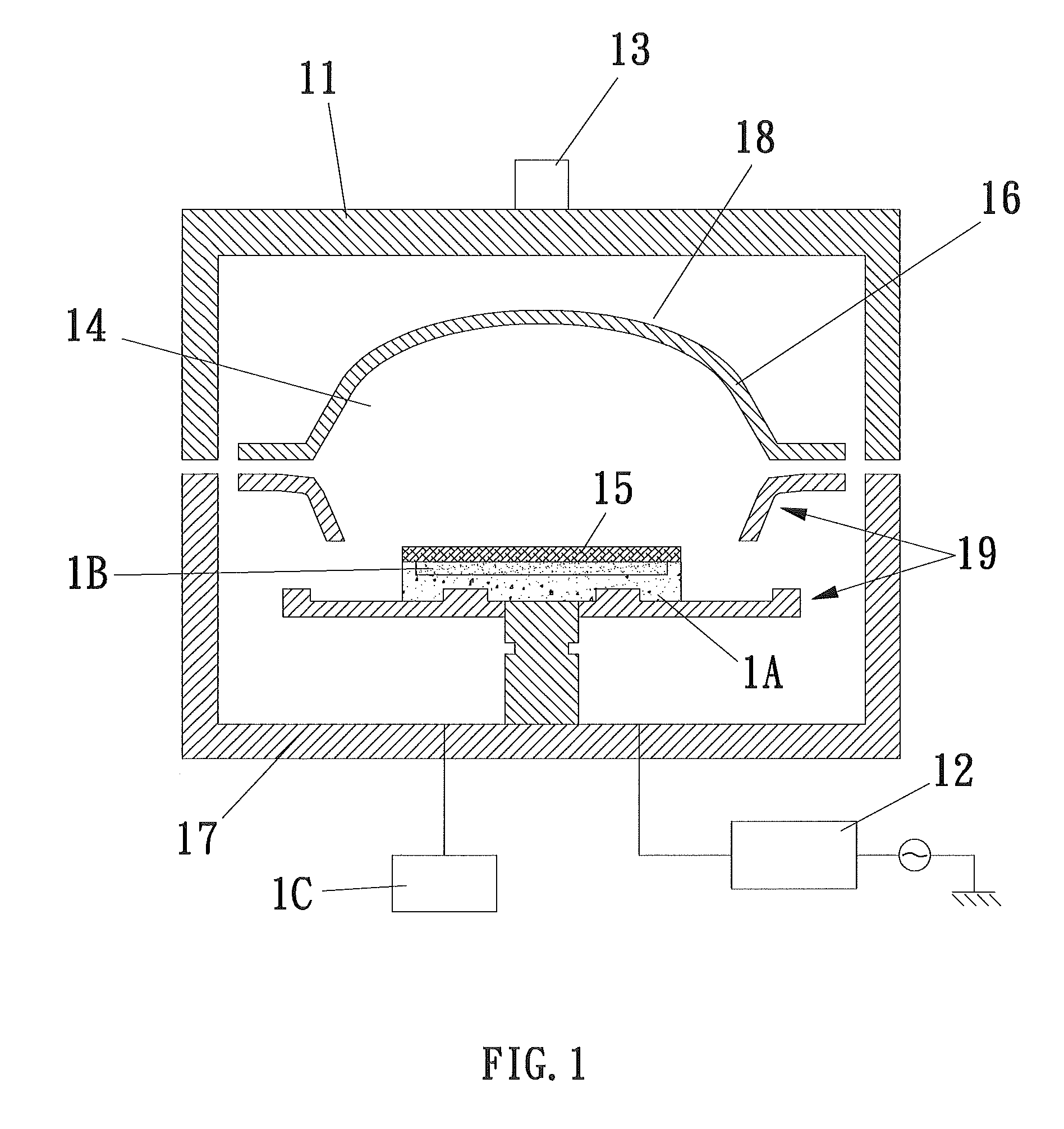
[0016]Please refer to FIG. 1 that is a sectional view showing the structure of a common and typical plasma bombardment cleaning reaction chamber used in the manufacturing process for semiconductor devices, flat displays, and solar panels. As shown, the reaction chamber is provided with an energy source 12. In the illustrated embodiment, the energy source is radio frequency. That is, the energy source herein is a radio frequency (RF) source 13 provided on the top 11 of the cleaning reaction chamber. In the reaction chamber, there is an internal space 14 defined among different structural parts of the reaction chamber for accommodating a substrate 15 to be treated in a reaction occurred in the reaction chamber. The substrate 15 may be of different materials, such as a silicon wafer. The internal space 14 may be maintained as an effectively closed vacuum environment, in which plasma 16 required for a cleaning process is produced. The substrate 15 to be cleaned is subjected to plasma bo...


PUM

PropertyMeasurementUnit
thicknessaaaaaaaaaa
thicknessaaaaaaaaaa
thicknessaaaaaaaaaa

Abstract

In a reaction chamber for manufacturing semiconductor devices, flat displays, solar panels, a thermal spray ceramic coating with special geometric patterns is provided on structural parts in the reaction chamber. The geometric patterns of the ceramic coating are designed according to operating conditions in the reaction chamber, such as the energy source and the plasma producing gases being used, the intended plasma distribution and subsequent reactions in the reaction chamber, and compositions of the ceramic coating. To form the ceramic coating with special geometric patterns, a special masking process is adopted, and, after the forming of the ceramic coating with desired geometric patterns, a post grit blasting treatment is conducted to obtain a desired surface coarseness for the ceramic coating.

Description

FIELD OF THE INVENTION[0001]The present invention relates to a reaction chamber for manufacturing semiconductors, flat displays, and solar energy cells, and more particularly to reaction chamber structural parts with a ceramic coating; and the present invention also relates to a method for forming the ceramic coating on these structural parts.BACKGROUND OF THE INVENTION[0002]FIG. 1 is a sectional view showing the structure of a typical pre-cleaning reaction chamber. As shown, the pre-cleaning reaction chamber is internally provided with a dome 18 made of quartz for covering a plasma bombardment space 14. When a radio frequency (RF) source 13 is mounted on a top 11 of the reaction chamber to serve as an energy source, plasma 16 may be produced in the plasma bombardment space 14 through the reaction of plasma source gases 17 which are supplied into the reaction chamber. The plasma source gases 17 may include argon (Ar), helium (He), and hydrogen (H2). As a result, a reaction target 15...

Claims


Application Information

Patent Timeline
Patent Type & Authority Applications(United States)
IPC IPC(8): B01J19/00B05D1/32
CPCC23C4/005C23C14/564C23C4/18C23C4/105C23C4/01C23C4/11
Inventor WU, BO-CHENCHOU, TSUNG-CHIHTENG, JEN-YUNGCHERN, SHYUE-JER
Owner SHIH HER TECH
Why Eureka
Try Eureka