
Apparatus and A Method for Solar Tracking and Concentration af Incident Solar Radiation for Power Generation

a technology of solar energy and solar energy, applied in the field of solar power generation technology, can solve the problems of inconvenient design, negative environmental impact inability to meet the cost of solar power harnessing methods,

Inactive Publication Date: 2009-12-24
BANERJEE RAJARSHI
View PDF31 Cites 35 Cited by
  • Summary
  • Abstract
  • Description
  • Claims
  • Application Information

AI Technical Summary

Benefits of technology

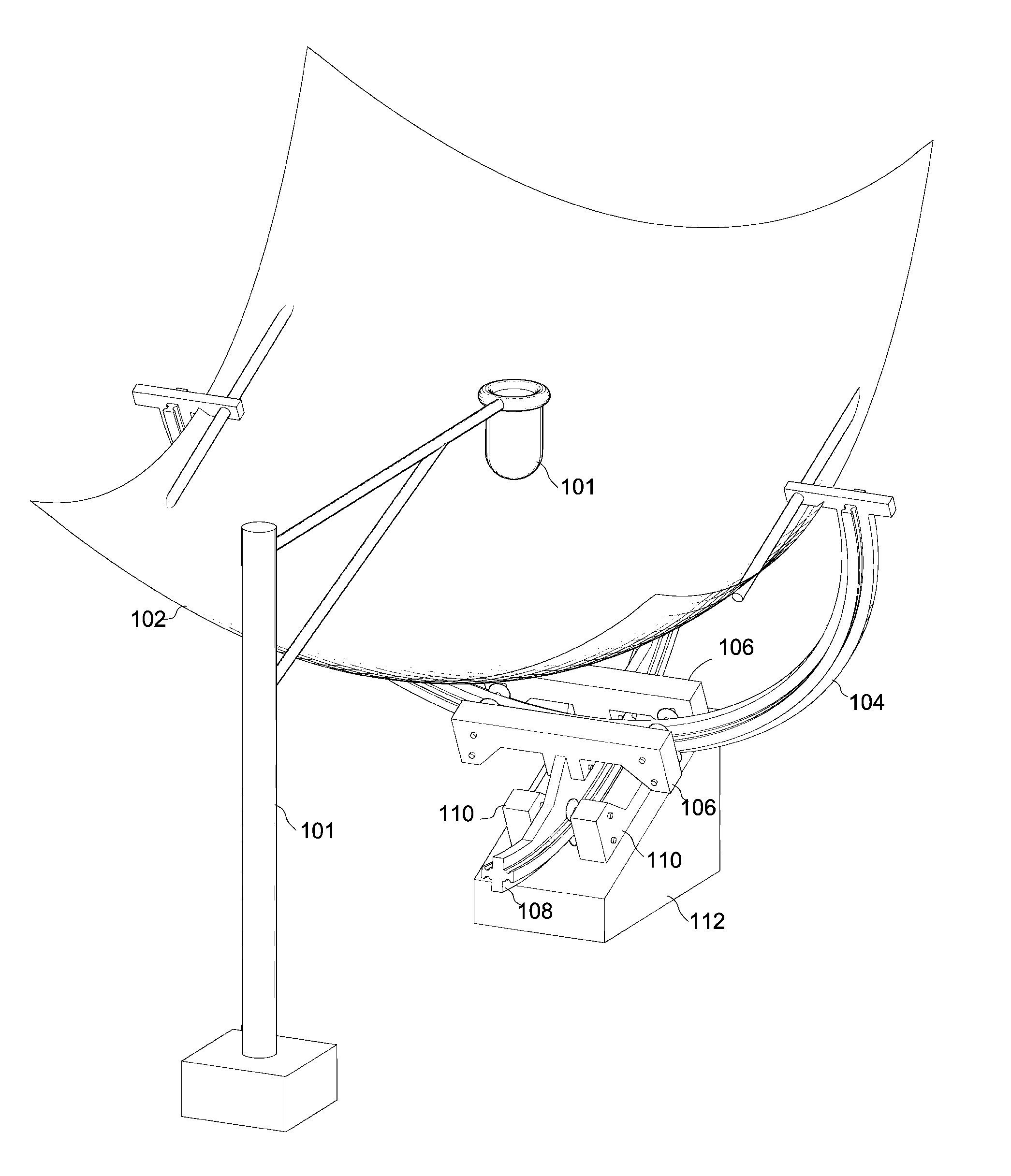
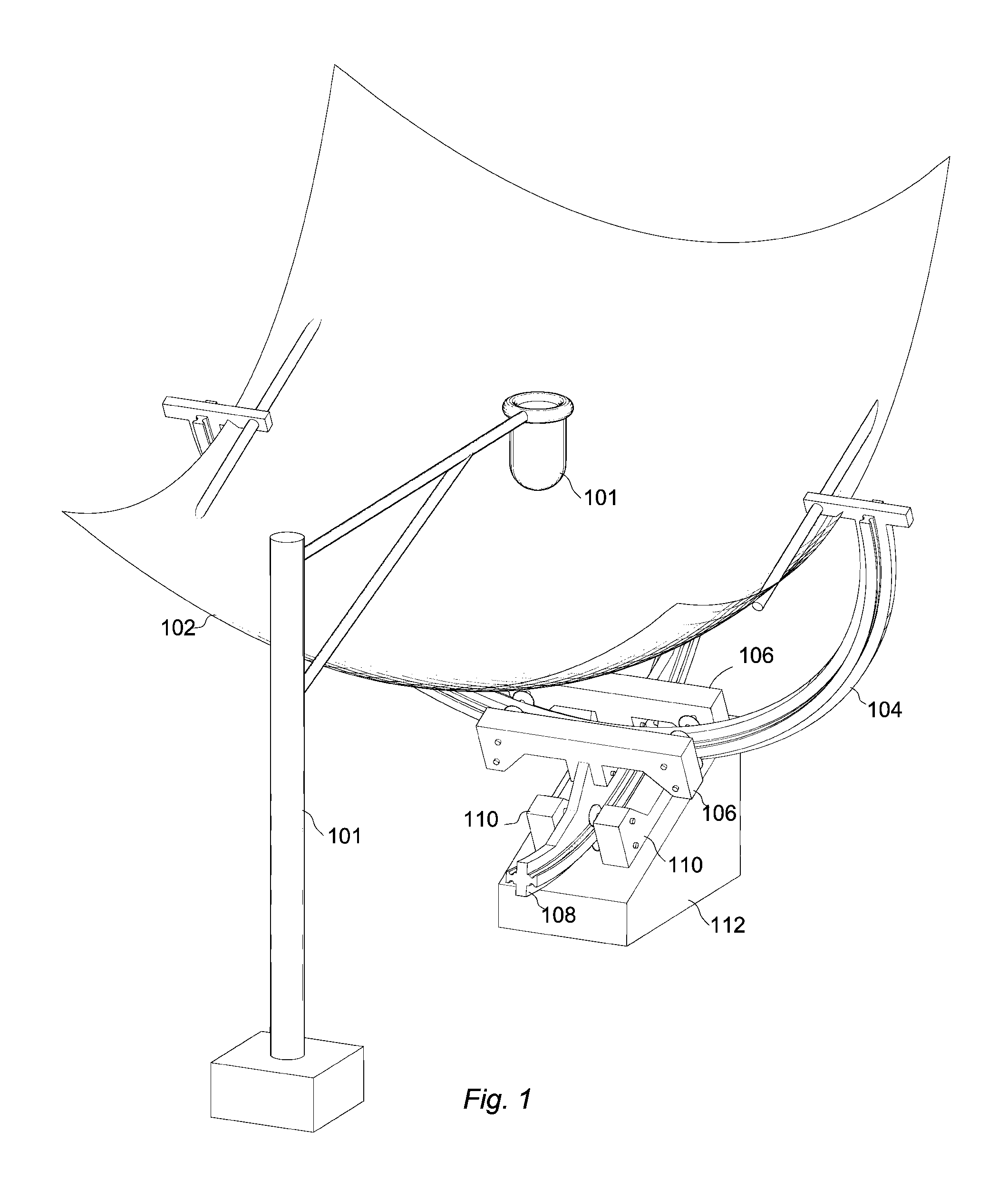
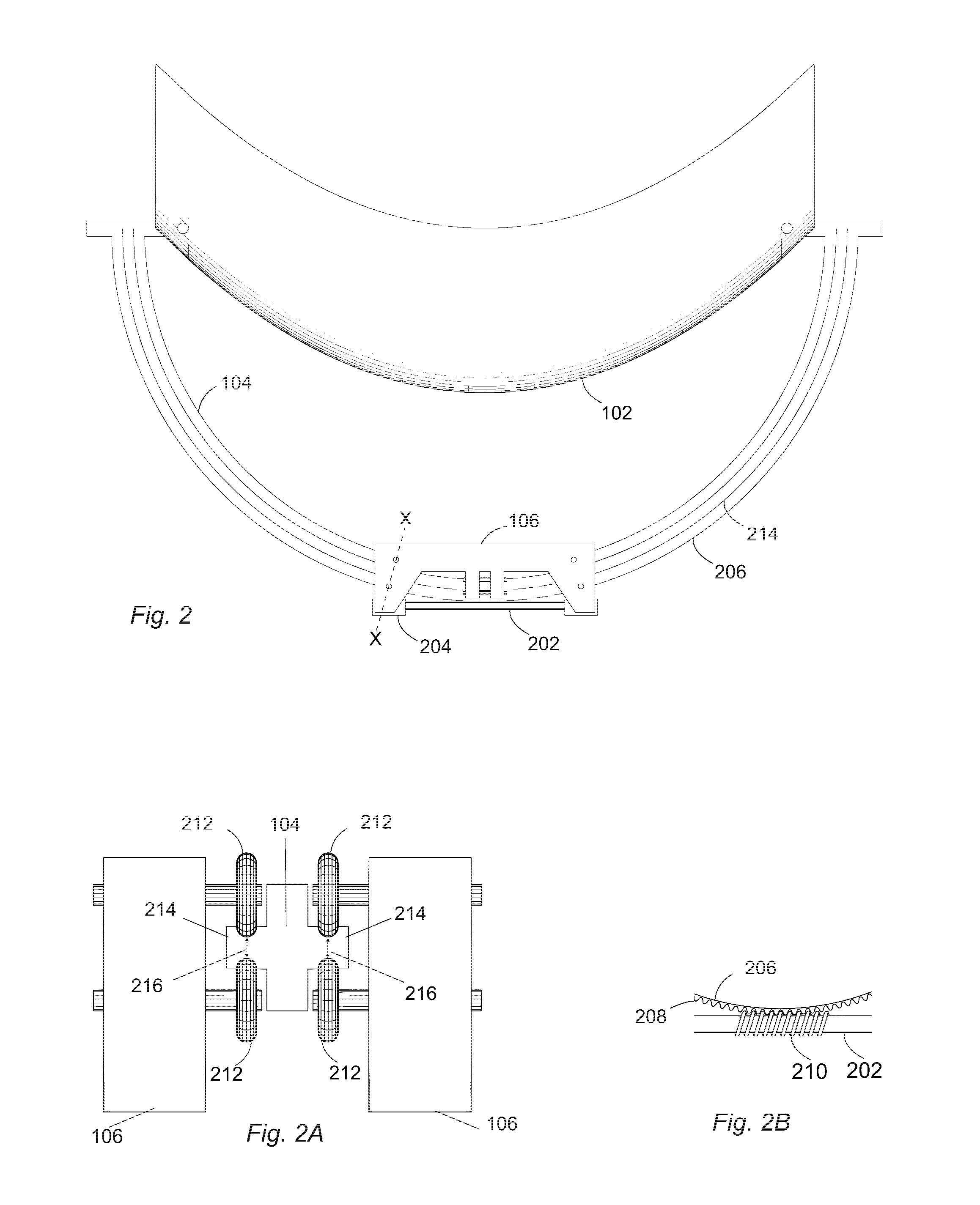
[0036]In another embodiment a method for solar tracking and concentration of incident solar radiation for power generation is presented. The method includes the steps of tracking a sun with a solar tracking system including a right ascension track having a rim and a declination track having a rim for dual axis solar tracking along equatorial coordinates of the sun, wherein the right ascension track and the declination track are driven at their respective rims during the tracking. The method includes moving an optical concentrator system to concentrate the incident solar radiation into a stationary focal point, wherein the optical concentrator system is moved by the solar tracking system. The method includes collecting concentrated incident solar radiation with a radiation collection device disposed proximate the

Problems solved by technology

Fossil fuels are a limited resource and their use has a negative impact on the environment.
Currently, means of harnessing solar power are not cost competitive when compared with conventional sources of energy and there is an increasing effort to bridge the gap.
Unlike photovoltaic systems, thermal systems require some form of solar tracking and concentration for power generation, otherwise they are limited to just passive heating.
These systems suffer from non-optimal geometries wherein tracking and concentration are not fully realized resulting in energy losses inherent in the design, which are thus unavoidable.
Examples of these losses are optical losses such as cosine and spillage losses as well as thermal losses.
Lower overall efficiency also results in inefficient land usage, making these systems unsuitable where land is at a premium.
However, the high efficiency and output of these systems come at a high cost of the tracking, concentrating and power generation apparatus as well as associated engineering challenges that increase capital and operational costs still further.
Particularly in Dish-Thermal systems, a large component of these costs can be attributed to some common characteristics of related prior art and actual systems.
Several limitations that derive from having a moving point of focus are apparent in prior art.
One of these limitations is the constraints placed on the dimensions, weight and design of the flux receiving and power generation devices that can limit their efficiency.
Another limitation is asymmetric loading or efforts to counter it by configurations where the mass of the apparatus is distributed over a large range of radii resulting in high moment of inertia and high stopping and starting torque requirements from the motors that actuate tracking motion.
In addition to this, the tracking support structures need to support a large combined mass of the concentrator and power generation apparatus that can result in structural distortion and optical alignment inaccuracies.
An additional limitation to consider in the above art is the vibration loading of the support structures since Stirling engines operate at high RPM.
Yet another limitation of the above art, which is a function of having a moving receiver, is that the devices cannot be easily integrated with a cooling apparatus or with hybrid systems that have centralized power generation and heat storage devices that are fixed to the ground.
All these factors entail high costs for the motors, the support structures and the concentrator.
The high moment of inertia of the apparatus cannot be avoided because the concentrator needs to have a large aerial and radial spread to collect solar radiation; however, this limitation is heightened due to a majority of the designs implementing axial drives as mentioned.
In such systems, additional structures for high gear reduction and indirect drives are often required and the accuracy and overall torque, particularly starting and stopping torque required of the motors are also high, which entails high cost.
Closed loop systems cannot track when clouds cover the sun.
Open loop systems are overly complex due to the non-uniform motion of the sun along altitude and azimuth axes which require the coordinates to be computed at all times by solving ephemeris equations and often still require additional means for correction of step, drift and structural distortion errors.
Both closed and open loop systems for altitude-azimuth trackers are expensive, require high maintenance, high precision motors and means of controlling step and drift errors because the motors need to step through non-uniform increments associated with altitude and azimuth tracking, necessitating high motor step rates combined with minute step magnitudes.
Furthermore, altitude-azimuth based tracking systems exclude the possibility of decoupling the diurnal and seasonal tracking of the sun.
Such systems also afford very limited scope for incorporating large gear reduction assemblies and lowering mechanical advantage.
However, this design implements axial drive systems and in general all gimbal-based designs afford very limited scope for the incorporation of large gear reduction assemblies.
This entails low mechanical advantage and the use of a larger amount of structural material.
The performance of this system is inferior to systems with rigid mirrors and true dual axis tracking, primarily because the region in space where sunlight is concentrated varies with the change in the curvature of the reflector.
However, this system implements altitude and azimuth based solar tracking and uses a large amount of material for the construction of the tracking apparatus and associated support structures.

Method used


Image

  • Apparatus and A Method for Solar Tracking and Concentration af Incident Solar Radiation for Power Generation
  • Apparatus and A Method for Solar Tracking and Concentration af Incident Solar Radiation for Power Generation
  • Apparatus and A Method for Solar Tracking and Concentration af Incident Solar Radiation for Power Generation

Examples


Embodiment Construction

[0037]The present invention is best understood by reference to the detailed figures and description set forth herein.

[0038]Embodiments of the invention are discussed below with reference to the Figures. However, those skilled in the art will readily appreciate that the detailed description given herein with respect to these figures is for explanatory purposes as the invention extends beyond these limited embodiments. For example, it should be appreciated that those skilled in the art will, in light of the teachings of the present invention, recognize a multiplicity of alternate and suitable approaches, depending upon the needs of the particular application, to implement the functionality of any given detail described herein, beyond the particular implementation choices in the following embodiments described and shown. That is, there are numerous modifications and variations of the invention that are too numerous to be listed but that all fit within the scope of the invention. Also, ...


PUM

PropertyMeasurementUnit
Concentrationaaaaaaaaaa
Heataaaaaaaaaa
Solar radiationaaaaaaaaaa

Abstract

A method and an apparatus are presented for solar tracking and concentration of incident solar radiation for power generation. The apparatus includes a solar tracking system, an optical concentrator system and a radiation collection device. The solar tracking system includes a right ascension track and a declination track for dual axis solar tracking along equatorial coordinates of the sun, wherein the right ascension track and the declination track are driven at their respective rims. The optical concentrator system is moved by the solar tracking system to concentrate the incident solar radiation into a stationary focal point. The radiation collection device couples concentrated incident solar radiation to a power generation means. The radiation collection device is disposed proximate the stationary focal point to collect the incident solar radiation.

Description

CROSS-REFERENCE TO RELATED APPLICATIONS[0001]The present Utility patent application claims priority benefit of the U.S. provisional application for patent Ser. No. 61 / 132,995 filed on Jun. 24, 2008 under 35 U.S.C. 119(e). The contents of this related provisional application are incorporated herein by reference for all purposes.FEDERALLY SPONSORED RESEARCH OR DEVELOPMENT[0002]Not applicable.REFERENCE TO SEQUENCE LISTING, A TABLE, OR A COMPUTER LISTING APPENDIX[0003]Not applicable.COPYRIGHT NOTICE[0004]A portion of the disclosure of this patent document contains material that is subject to copyright protection. The copyright owner has no objection to the facsimile reproduction by anyone of the patent document or patent disclosure as it appears in the Patent and Trademark Office, patent file or records, but otherwise reserves all copyright rights whatsoever.FIELD OF THE INVENTION[0005]The present invention relates generally to solar power generation technology. More particularly, the i...

Claims


Application Information

Patent Timeline
IPC IPC(8): F24J2/10F24J2/38B23P11/00F24S23/70F24S50/20
CPCF24J2/12F24J2/5417Y10T29/49826Y02E10/42Y02E10/47F24J2002/5475F24S23/71F24S2030/14F24S30/45Y02E10/40
Inventor BANERJEE, RAJARSHI
Owner BANERJEE RAJARSHI
Learn More