Patient flow management and analysis using location tracking
- Summary
- Abstract
- Description
- Claims
- Application Information
AI Technical Summary
Benefits of technology
Problems solved by technology
Method used
Image

Examples
Embodiment Construction
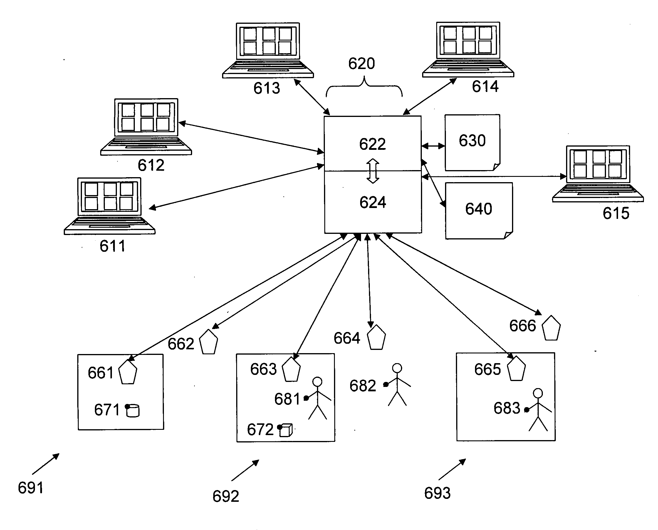
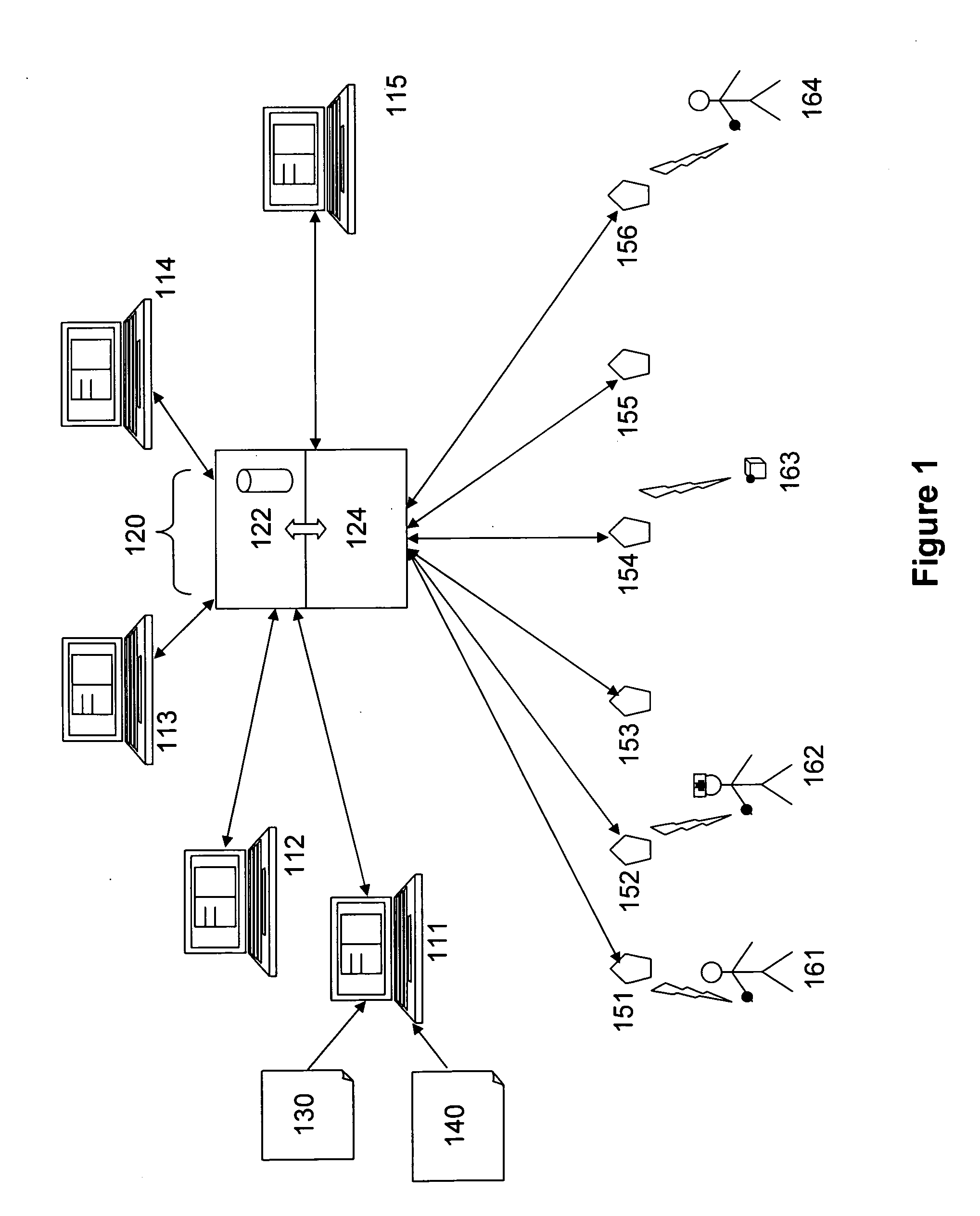
[0027]In FIG. 1, a patient flow management system generally has a management computer 120 functionally connected to user interfaces 111, 112, 113, 114, 115 and to wireless detectors 151, 152, 153, 154, 155, 156. Management computer 120 is shown as being connected to the user interfaces and the wireless detectors through bi-directional Ethernet wires, but could also be connected through a variety of means without departing from the scope of the current invention, including with wireless devices or unidirectional connection systems.
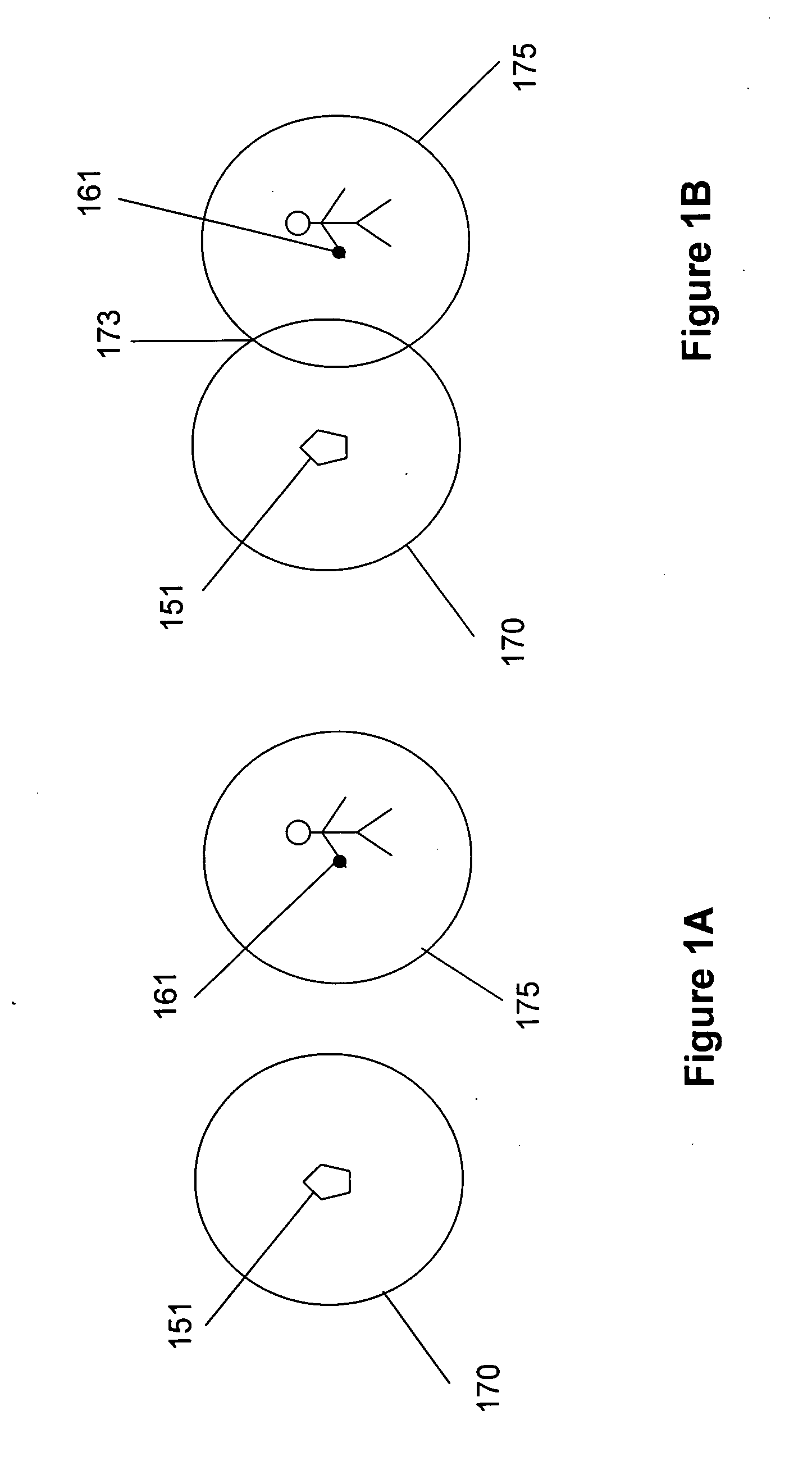
[0028]Management computer 120 has a patient flow engine 122 that tracks the patients' progress through patient flow patterns by communicating with location engine 124 that tracks tags that are detected by wireless detectors 151, 152, 153, 154, 155, 156. Each wireless detector monitors an area of the medical facility to detect patient tags entering that area. When a patient tag enters an area that is being monitored by the wireless detector, the detector can...
PUM
 Abstract
Description
Claims
Application Information
 - Generate Ideas
- Intellectual Property
- Life Sciences
- Materials
- Tech Scout
- Unparalleled Data Quality
- Higher Quality Content
- 60% Fewer Hallucinations
Browse by: Latest US Patents, China's latest patents, Technical Efficacy Thesaurus, Application Domain, Technology Topic, Popular Technical Reports.
© 2025 PatSnap. All rights reserved.Legal|Privacy policy|Modern Slavery Act Transparency Statement|Sitemap|About US| Contact US: help@patsnap.com