Visual inspection apparatus, visual inspection method, and peripheral edge inspection unit that can be mounted on visual inspection apparatus.

a technology of visual inspection apparatus and peripheral edge, which is applied in the direction of measuring devices, scientific instruments, instruments, etc., can solve the problems of workpiece fracture during circuit manufacture, workpiece warpage or internal stress, and prolonged takt time, so as to reduce the time and effort of transfer, reduce the takt time of inspection, and reduce the installation area.

Inactive Publication Date: 2009-12-24
OLYMPUS CORP
View PDF6 Cites 12 Cited by
  • Summary
  • Abstract
  • Description
  • Claims
  • Application Information

AI Technical Summary

Benefits of technology

[0010]The invention has been made in view of the above circumstances. It is therefore a main object of the invention is to reduce takt time, miniaturize the apparatus, and simplify the configuration of the apparatus in performing macro inspection, micro inspection, and peripheral edge inspection.
[0016]According to the present invention, in the visual inspection apparatus that has the visual inspection section that is used to allow visual inspection of the surface of a workpiece, the holding unit that holds the workpiece is shared by the visual inspection of the surface of the workpiece, and the peripheral edge inspection that inspects the peripheral edge of the workpiece. Thus, it is possible to perform the visual inspection and peripheral edge inspection while the workpiece is held by the holding unit, without performing transfer of the workpiece. Furthermore, compared with a case where apparatuses are configured independently, the installation area can be made small. Moreover, since the distance at which the workpiece is moved, and the time and effort for transfer can be omitted, the tact time of inspection can be reduced.

Problems solved by technology

Further, when circuits, etc. are formed on a workpiece, warpage or internal stress may be caused in the workpiece due to heat treatment, etc.
If such warpage and internal stress become large, the workpiece may be fractured during manufacture of the circuits.
However, in order to carry out the macro inspection, micro inspection, and peripheral edge inspection, there are problems in that a wafer must be replaced and moved by a machine, a loader, etc., between the visual inspection apparatus disclosed in Patent Document 1, and the visual inspection apparatuses disclosed in Patent Document 2, causing prolonged takt time.
However, replacement of a workpiece is required even in such a case.

Method used


Image

  • Visual inspection apparatus, visual inspection method, and peripheral edge inspection unit that can be mounted on visual inspection apparatus.
  • Visual inspection apparatus, visual inspection method, and peripheral edge inspection unit that can be mounted on visual inspection apparatus.
  • Visual inspection apparatus, visual inspection method, and peripheral edge inspection unit that can be mounted on visual inspection apparatus.

Examples


first embodiment

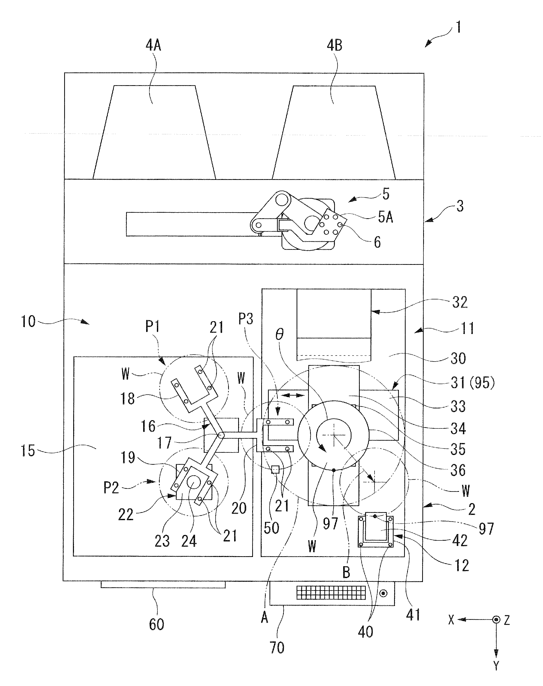
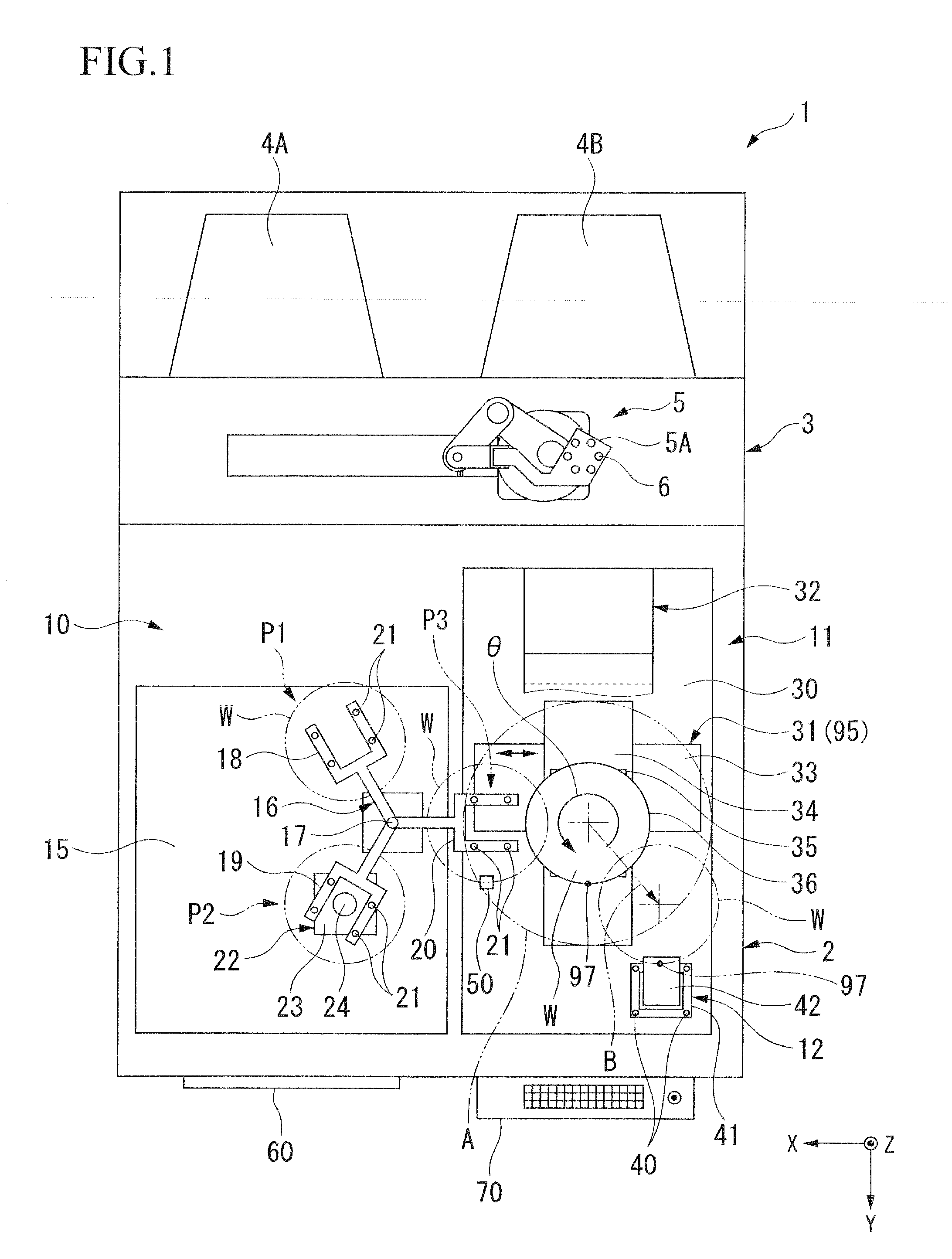
[0078]As shown in FIG. 1, a visual inspection apparatus 1 has an inspection section 2 provided at the front (a lower part in FIG. 1) that faces an inspector, and a loader part 3 is connected to the back side of the inspection section 2. In the loader part 3, two wafer carriers 4A and 4B that receive semiconductor wafers W (hereinafter referred to as “wafer W”) that are workpieces are connected side by side. In addition, the wafer carriers 4A and 4B can receive a plurality of wafers W at a predetermined pitch in a vertical direction. For example, a non-inspected wafer W is received in the wafer carrier 4A, and an inspected wafer W is received in the wafer carrier 4B. Moreover, the wafer carriers 4A and 4B can be independently attached to and detached from the loader part 3.

[0079]The loader part 3 has an automated transport unit 5. The automated transport unit 5 includes a multi-segmented robotic arm, and a hand 5A at a tip of the robotic arm is provided with suction holes 6 that hold...

second embodiment

[0111]A second embodiment is characterized in that the peripheral edge inspection section is provided in the macro-inspection section in which inspection is performed by visual observation. Other configurations and operations are the same as those of the first embodiment.

[0112]As shown in FIG. 4, in a visual inspection apparatus 51, a peripheral edge inspection section 61 (outer edge inspection unit) is detachably provided in the loading plate 15 of the macro-inspection section 10. The peripheral edge inspection section 61 has a anchor 62 fixed to the loading plate 15, a uniaxial stage 63, and a base part 42 attached to the enlarged image acquisition part 44. The base part 42 is attached so that it can be brought close to or spaced apart from the position P2. As shown in FIG. 5, in an inspection position where the base part 42 is brought closest to the position P2, the peripheral edge of the wafer W held horizontally by the macro-inspection unit 22 enter the recessed part 43. Furthe...

third embodiment

[0117]A third embodiment is characterized in that the peripheral edge inspection section is provided in an automatic micro-inspection section that automatically extracts a defect by image processing from an image captured by an imaging device.

[0118]Other configurations and operations are the same as those of the first embodiment. As shown in FIGS. 6 and 7, a visual inspection apparatus 71 has a loading plate 72 that is free from vibration, and an automatic micro-inspection section 73 is constructed in the loading plate 72. The automatic micro-inspection section 73 has an inspection stage 74, and an illumination device 75 and an imaging section 76 fixed so as to sandwich the inspection stage 74 in the X direction. The inspection stage 74 includes an X-axis stage 77, a Z-axis stage 78, and a rotary shaft 79 serving as a rotating mechanism, and a holding plate 80 that holds a wafer by suction-clamping is fixed on the rotary shaft 79. The illumination device 75 has a line light source t...


PUM

PropertyMeasurementUnit
observation angleaaaaaaaaaa
distanceaaaaaaaaaa
timeaaaaaaaaaa

Abstract

This visual inspection apparatus has a macro-inspection section and a micro-inspection section. In the micro-inspection section, a inspection stage and a microscope are loaded into a loading plate. The inspection stage can be moved in any directions of the X, Y, and Z directions, and can also be rotated in the θ direction. Moreover, a peripheral edge inspection section that acquires an enlarged image of a peripheral edge of wafer W is fixed to the loading plate. The peripheral edge inspection section is arranged so as to image the peripheral edge of wafer W held by the inspection stage.

Description

CROSS-REFERENCE TO RELATED APPLICATION[0001]The present application is a Continuation Application of U.S. application Ser. No. 11 / 977,880 filed Oct. 26, 2007, which is incorporated herein by reference and which is a Continuation of International Application No. PCT / JP2006308759 filed Apr. 26, 2006.BACKGROUND OF THE INVENTION[0002]1. Field of the Invention[0003]The present invention relates to a visual inspection apparatus used to inspect the appearance of a workpiece, a visual inspection method, and a peripheral edge inspection unit that can be mounted on such a visual inspection apparatus and used to inspect the peripheral edge of the workpiece.[0004]2. Description of Related Art[0005]When patterns, such as circuits, on a workpiece, such as a semiconductor wafer, are formed, a visual inspection apparatus that inspects the existence of a defect on the surface of the workpiece is used. As this type of visual inspection apparatus, there is an inspection apparatus (for example, refer t...

Claims


Application Information

Patent Timeline
Patent Type & Authority Applications(United States)
IPC IPC(8): G01N21/00
CPCG01N21/9503
Inventor YOKOTA, ATSUTOSHIHEBIISHI, HIROYASUDOSAKA, SHINICHI
Owner OLYMPUS CORP
Why Eureka
Try Eureka