Optical head and optical disk apparatus

a technology of optical disk and optical head, which is applied in the direction of data recording, instruments, information storage, etc., can solve the problems of affecting etc., and achieving the effect of ensuring the quality of optical disk

Inactive Publication Date: 2009-12-24
HITACHI CONSUMER ELECTRONICS CORP
View PDF14 Cites 18 Cited by
  • Summary
  • Abstract
  • Description
  • Claims
  • Application Information

AI Technical Summary

Benefits of technology

[0011]An object of the present invention is to provide an interference type optical head that has an optical path length adjusting function and a signal amplification effect.
[0014]The optical path length of the first light beam varies not only with the surface position fluctuation of the optical disk, but also when, for example, the recording layer to be read is changed in a multi-layered optical disk comprising a plurality of recording layers, and the like. In order to prevent the light reflected from the plurality of recording layers from interfering, thus subjecting the readout signal to disturbance, the gap between recording layers must at least be kept at a certain level in a multi-layered optical disk. The gap between recording layers in currently commercially available optical disks is on the order several tens of μm. The gap between the farthest two recording layers in multi-layered optical disks, too, would have to be about the same or greater. Therefore, the change in the optical path length of the first light beam when the recording layer to be read is changed would be on the order of several tens of μm to several hundreds of μm. Thus, the light interference effect is weakened, thereby causing signal quality degradation. For this reason, a means that adjusts the optical path length of the first light beam or of the second light beam is provided, and adjustment is so performed that the optical path length difference would not vary even when the recording layer to be read is changed.
[0015]According to the present invention, it is possible to provide an interference type optical head and an optical disk apparatus which can be manufactured in sizes comparable to conventional optical heads, are capable of reading multi-layered optical disks and optical disks of a plurality of standards, and have a signal amplification effect.

Problems solved by technology

However, if this is done through, for example, an actuator such as a voice coil motor or the like, the optical axis direction would change due to the vibration caused by the driving thereof.
As a result, the degree of interference with the signal light would drop significantly, and it would become impossible to obtain signals that are amplified properly.
However, a device that would exhibit performance commensurate with the magnitude and speed of the surface position fluctuation of optical disks mentioned above would not be suitable for incorporation into an optical head in terms of its size.

Method used


Image

  • Optical head and optical disk apparatus
  • Optical head and optical disk apparatus
  • Optical head and optical disk apparatus

Examples


embodiment 1

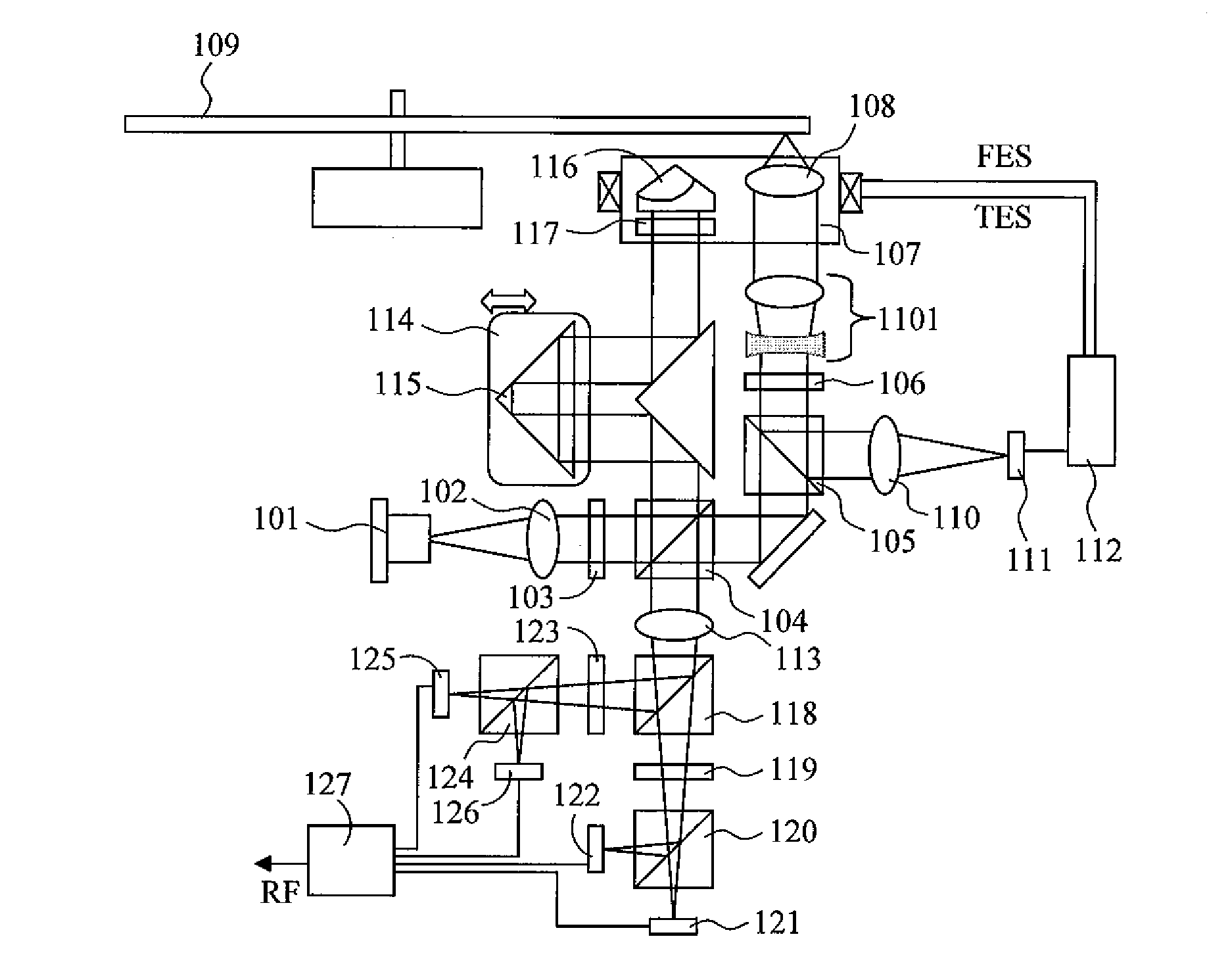
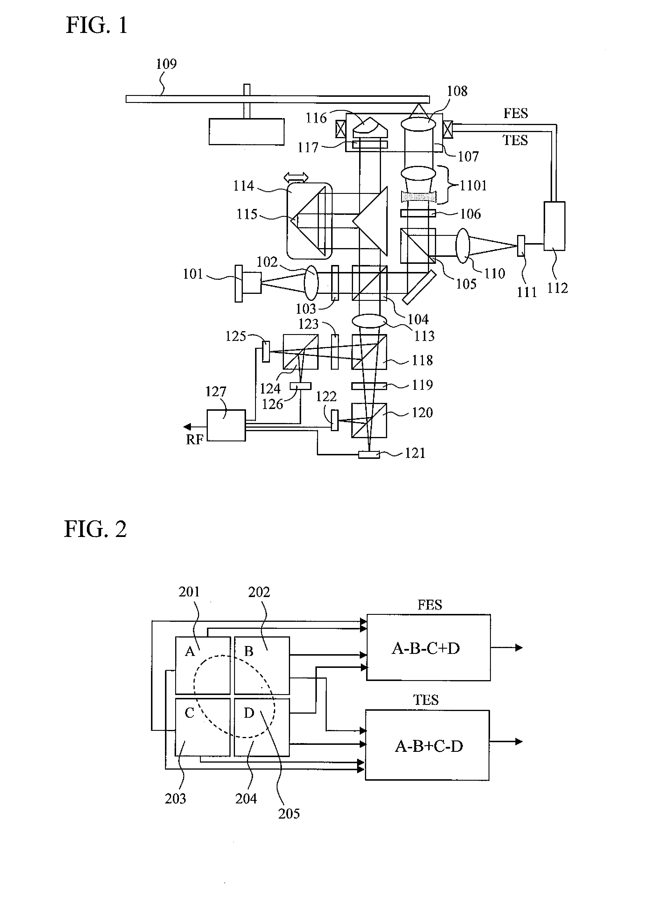
[0033]FIG. 1 is a schematic view indicating a basic embodiment of an optical head of the present invention. Light from a semiconductor laser 101 is collimated by a collimation lens 102, is transmitted through a half waveplate 103, and enters a polarization beam splitter 104. The polarization beam splitter 104 has functions of transmitting substantially 100% of the p-polarization (hereinafter referred to as horizontal polarization) incident on the splitting surface, and of reflecting substantially 100% of the s-polarization (hereinafter referred to as vertical polarization) incident on the splitting surface. Here, the intensity ratio of transmitted light to reflected light can be adjusted by adjusting the rotation angle of the half waveplate about the optical axis. The transmitted light first enters a special polarization beam splitter 105. The special polarization beam splitter 105 has such a property where 100% of the horizontal polarization is transmitted, and the vertical polariz...

embodiment 2

[0054]As another embodiment, FIG. 7 is a schematic diagram of an optical head that uses a pair of wedge prisms 701 and 702 for optical path length difference adjustment between the signal light and the reference light. In this case, optical path length difference adjustment may be performed by parallel movement of one of the wedge prisms in the optical axis direction or in a direction that is perpendicular to the optical axis (the direction indicated by the arrow in the figure). By using a wedge prism pair, it becomes unnecessary to fold back the optical path as in Embodiment 1. Thus, a reduction in the size of the optical system can be realized.

[0055]In addition, in the present scheme, displacement of the beam occurs, and the degree of displacement varies with the adjustment of the optical path length. However, this can be reduced to a practically negligible degree by appropriately setting the angle, medium, and the like of the wedge prisms. By way of example, a case is considered ...

embodiment 3

[0057]As another embodiment, FIG. 11 is a schematic diagram of an optical head that simultaneously performs spherical aberration correction and optical path length difference adjustment of the signal light. In general, when a multi-layered optical disk is read, the distance traveled through the internal medium of the optical disk by the light varies with each recording layer. As a result, the amount of spherical aberration occurring at the optical disk varies. For this reason, the beam expander 1101 is inserted in the optical path of the signal light, and one of a pair of lenses forming the beam expander 1101 is moved in the optical axis direction. Thus, spherical aberration that cancels out the spherical aberration occurring internally in the optical disk is caused, thereby performing adjustment to make spherical aberration smallest for all recording layers.

[0058]In the present embodiment, the lens mentioned above and a component used for optical path length difference adjustment a...


PUM

PropertyMeasurementUnit
optical path lengthaaaaaaaaaa
wavelengthaaaaaaaaaa
coherence lengthaaaaaaaaaa

Abstract

There are provided an interference type optical head and an optical disk apparatus, which have a signal amplification effect and which can be manufactured in sizes comparable to conventional optical heads. In an optical disk apparatus that performs signal amplification by making a light, which is used as a reference light without being irradiated on an optical disk and, interfere with reflected light from the optical disk, a corner cube prism that reflects the reference light is mounted on the same actuator as an objective lens. Further, there is provided a movable portion that adjusts the optical path length of the interfering light in accordance with the kind of optical disk being read and the recording layer being read. A wedge prism may be used for the movable portion, and a spherical aberration correction lens and an optical path length adjusting component may be moved integrally. Thus, a stable amplification effect may be obtained while keeping the overall size comparable to conventional apparatuses.

Description

BACKGROUND OF THE INVENTION[0001]1. Field of the Invention[0002]The present invention relates to achieving a higher S / N for readout signals of an optical disk apparatus.[0003]2. Background Art[0004]With the commercialization of Blu-ray Disc, which uses a blue laser diode and a high-NA objective lens, optical disks have more or less reached a limit in terms of the resolution of an optical system. The multi-layering of recording layers is viewed as holding promise in further increasing capacity in the future. With respect to such multi-layered optical disks, it is necessary that the detected quantity of light from each recording layer be substantially equal. Thus, the reflectivity from certain recording layers must be made smaller. However, along with the increase in the capacity of optical disks, data transfer speed also continues to increase due to the need for higher dubbing speed for video and the like. Thus, it is becoming difficult to secure an adequate S / N ratio for readout sig...

Claims


Application Information

Patent Timeline
Patent Type & Authority Applications(United States)
IPC IPC(8): G11B7/00
CPCG11B7/005G11B7/0956G11B7/1353G11B2007/0013G11B7/1359G11B7/1367G11B7/1378G11B7/1356
Inventor MIKAMI, HIDEHARUMIYAMOTO, HARUKAZUKUROKAWA, TAKAHIRO
Owner HITACHI CONSUMER ELECTRONICS CORP
Why Eureka
Try Eureka