Power-assisted control system for a rotorcraft

a technology of rotorcraft and control system, which is applied in the direction of rotors, marine propulsion, vessel construction, etc., can solve the problems of blade to flap, long mechanical connection, and inability to provide lift and propulsion to the main rotor

Active Publication Date: 2009-12-24
EUROCOPTER
View PDF3 Cites 11 Cited by
  • Summary
  • Abstract
  • Description
  • Claims
  • Application Information

AI Technical Summary

Benefits of technology

[0013]An aspect of the present invention is to provide a power-assisted control system for a rotorcraft that enables the above-mentioned limitations to

Problems solved by technology

Consequently, the main rotor does indeed provide lift and propulsion for a helicopter.
By varying the pitch of a blade, the lift it generates is varied and that has the consequence of causing the blade to flap.
This mechanical connection is thus in general very long and heavy.
Under such conditions, the pilot can have difficulty in moving the cyclic stick or the collective pitch lever, given the force that needs to be applied, particularly if the helicopter is itself heavy.
Nevertheless, that first s

Method used


Image

  • Power-assisted control system for a rotorcraft
  • Power-assisted control system for a rotorcraft
  • Power-assisted control system for a rotorcraft

Examples


first embodiment

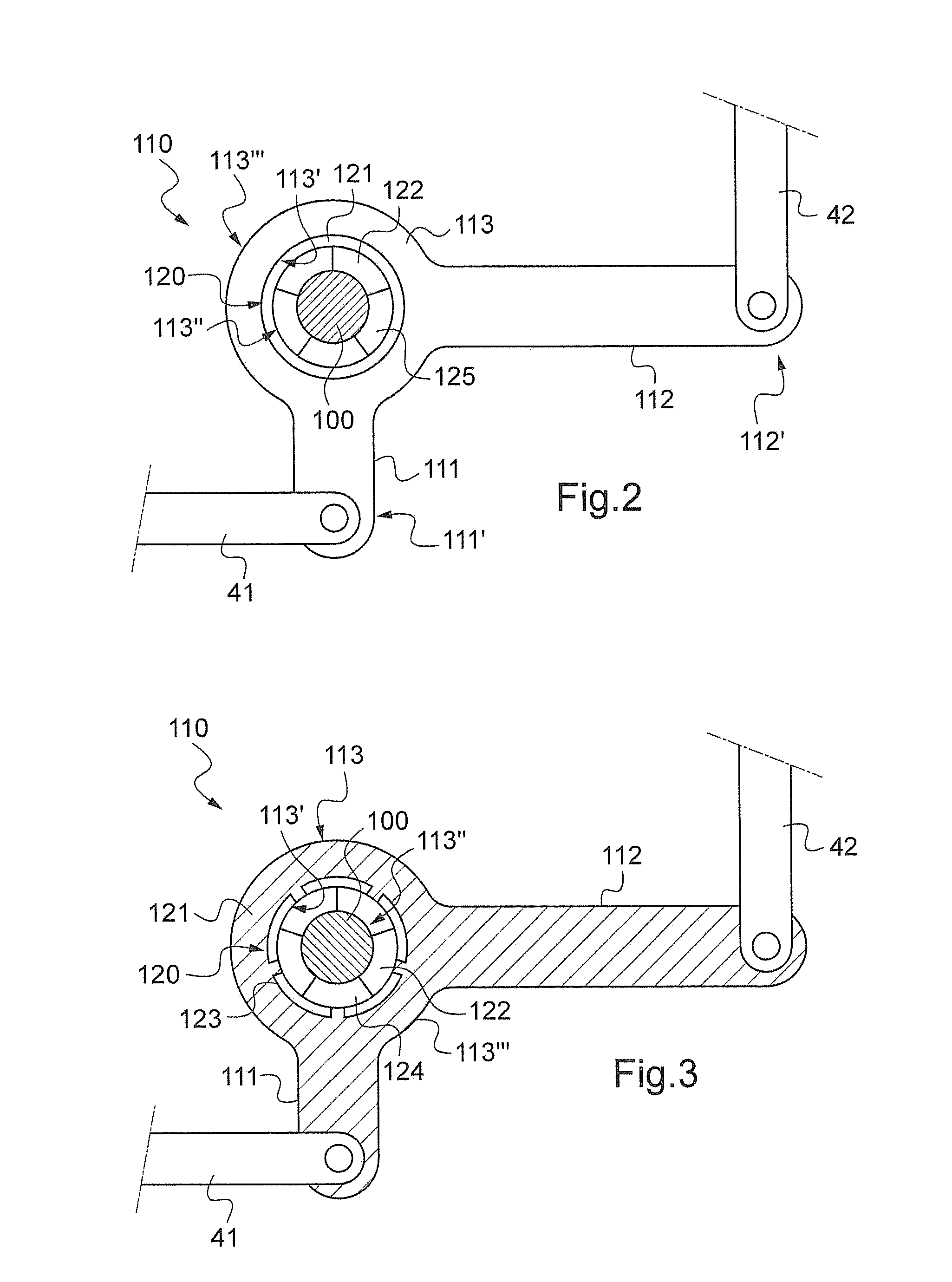
[0057]In the first embodiment shown diagrammatically in FIG. 2, the drive rotor 121 of the motor 120 is also arranged in the central orifice 113″ and it surrounds the stator 122. In addition, the drive rotor 121 is secured, e.g. by adhesive, to the inner periphery 113′ of the transition zone 113.

[0058]Since the motor is a brushless motor, the stator 122 is provided with a plurality of electromagnetic modules 125, while the drive rotor 121 is magnetized. It should be observed that another configuration is possible, the stator 122 being magnetized while the drive rotor 121 is provided with a plurality of electromagnetic modules 125.

[0059]On being powered sequentially, the electromagnetic modules 125 create an electromagnetic field that drives the drive rotor 121 of the motor 120 to turn about the stator 122, and thus about the support shaft 100.

[0060]Similarly, the body of the crank means 110 performs an identical rotary movement. Since the drive rotor 121 of the motor 120 can turn ab...

second embodiment

[0061]In the second embodiment shown in FIG. 3, the transition zone 113 of the crank means constitute the drive rotor 121 of the motor 120. The inner periphery 113′ is then magnetized to act as the drive rotor of the motor 120. Consequently, the inner periphery 113′ may be fitted with a plurality of magnets 123.

[0062]Thus, in the first embodiment, the transition zone 113 of the crank means is secured to the drive rotor 121, whereas in the second embodiment, the transition zone 113 forms a component part as such of the drive rotor.

[0063]Finally, since the control system S includes motor control means, it is possible to envisage arranging the motor control means within the stator of the motor 120. The motor control means (not shown in the figures) are provided with members conventionally used by the person skilled in the art to enable turning movement of the drive rotor 121 to be controlled as a function of a signal received from a sensor 130 of the control system S.


PUM


Abstract

An assisted control system for controlling the attitude of a rotorcraft comprises a flight control device; at least one control member configured to act on an aerodynamic element of the rotorcraft; a mechanical connection connecting the flight control device to the at least one control member, the mechanical connection including at least one connecting rod moveable in translation, a crank device pivotably disposed about a stationary support shaft passing through the crank device, and a motor including a drive rotor and a stator configured to facilitate a pivoting movement of the crank device about the stationary support; a motor control device configured to control a rotation of the drive rotor relative to the stator; and at least one sensor configured to measure information representative of an operation performed by the flight control device under pilot control and to deliver a signal to the motor control device.

Description

[0001]Priority is claimed to French Patent Application No. FR 08 02687, filed on May 19, 2008, the entire disclosure of which is incorporated by reference herein.[0002]The present invention relates to a power-assisted control system for a rotorcraft, more particularly a helicopter. The invention is thus situated in the narrow field of rotorcraft control systems, in particular because of the specific features encountered in the field of aviation, e.g. as associated with safety requirements and environmental conditions.BACKGROUND[0003]A helicopter commonly has a main lift and propulsion rotor that is provided with a plurality of blades. The blades of the main rotor describe a very open cone having its plane of rotation perpendicular to the general lift generated by said main rotor. This general lift of the main rotor can then be resolved into a vertical lift force and a horizontal force that drives the helicopter in translation. Consequently, the main rotor does indeed provide lift an...

Claims


Application Information

Patent Timeline
IPC IPC(8): F01D7/00
CPCB64C13/30B64C27/59
Inventor GARCIN, PATRICEVINCENT, PHILIPPEBROCHER, ERWAN
Owner EUROCOPTER
Why Eureka
Try Eureka