
Loss reduction in a coaxial network

Inactive Publication Date: 2009-12-24
TECHNETIX GROUP
View PDF3 Cites 61 Cited by
  • Summary
  • Abstract
  • Description
  • Claims
  • Application Information

AI Technical Summary

Benefits of technology

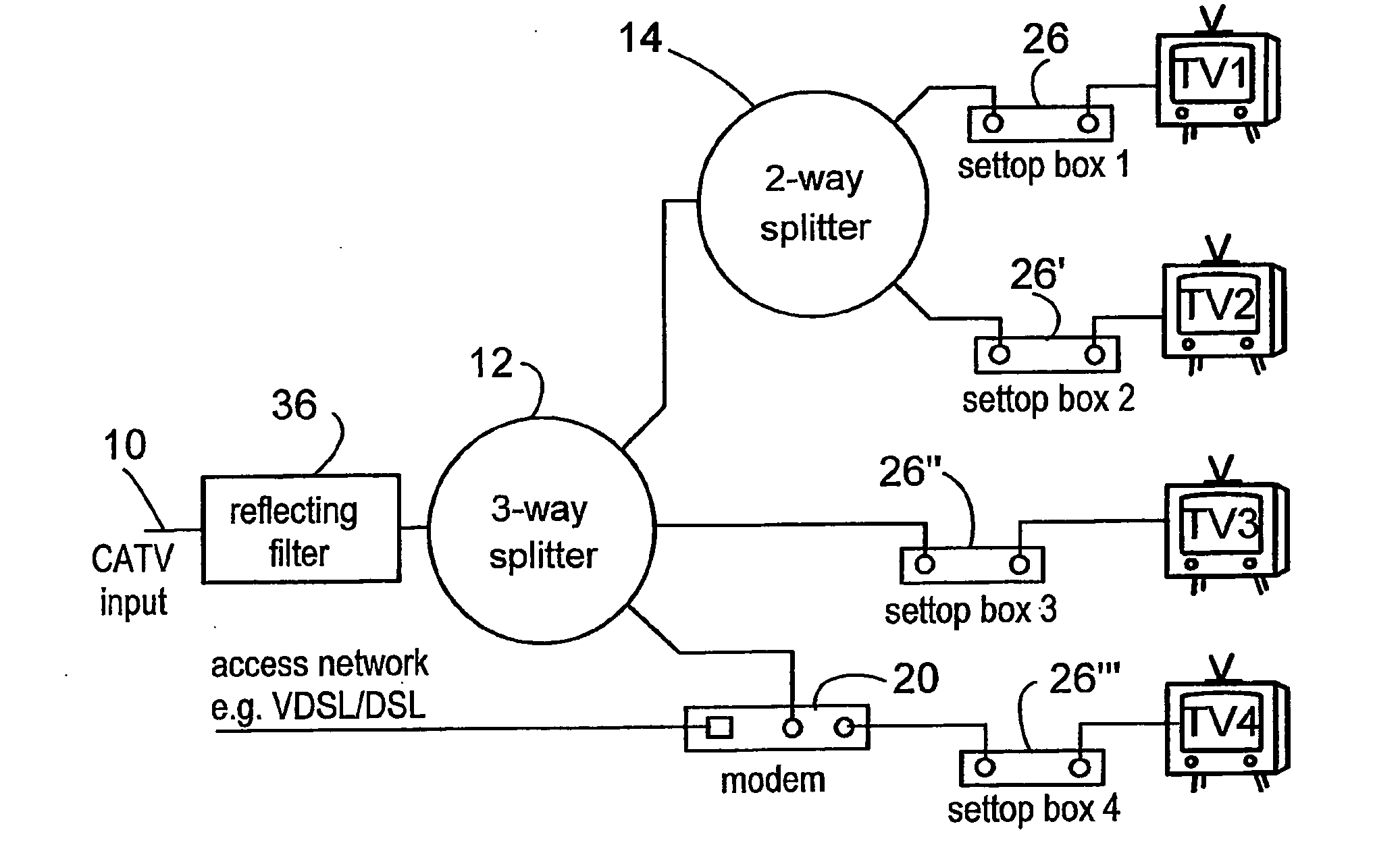
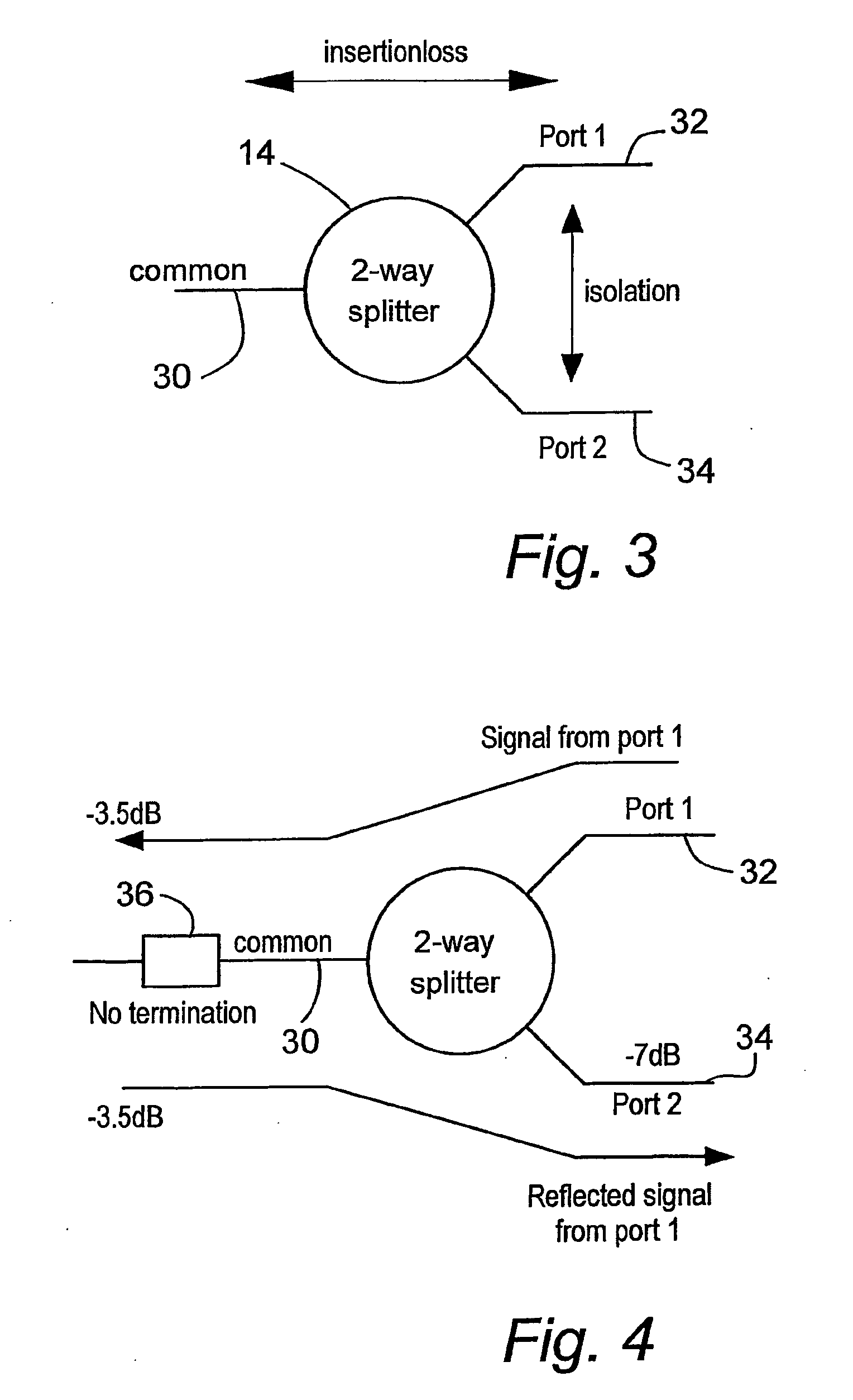
[0004]In accordance with the present invention, there is provided a coaxial network, typically an in-house network or a network within a dwelling such as a flat, comprising an input capable of connection to a cable or satellite television signal provider and which is connected to a signal splitting device for communicating a signal to a plurality of outlets in the form of subscriber equipment, wherein a filter is positioned between the input and the signal splitting device, the filter adapted to reflect signals in a frequency band used for data transfer thereby to reduce signal loss. By reflecting signals in a frequency band used for data transfer, whilst at the same time passing all other signals in a frequency pass band, the filter significantly reduces the signal loss between the plurality of outlets.

Problems solved by technology

Coaxial networks suffer from signal loss which becomes worse as the network adds additional outlet points.
However whilst there may be an access point within the home to the in-home coaxial network to which TV signals can be passed by a service provider connected to that input, signal losses in the in-home network can prevent the in-home network being operational where there are too many outlets to subscriber equipment, such as televisions and computers.

Method used


Image

  • Loss reduction in a coaxial network
  • Loss reduction in a coaxial network
  • Loss reduction in a coaxial network

Examples


Embodiment Construction

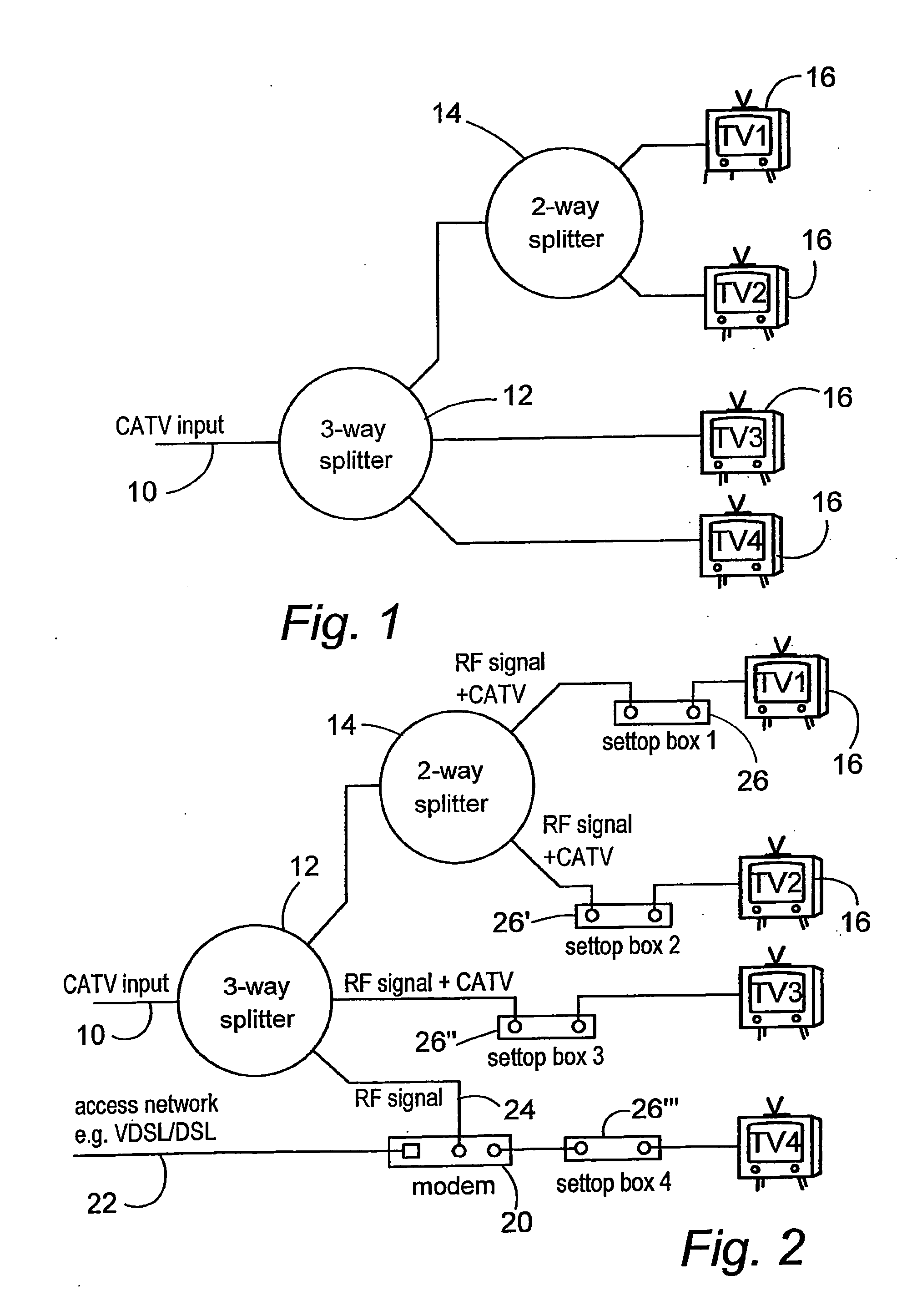
[0018]FIG. 1 shows a typical coaxial in-home TV network comprising an input 10 to which a cable television signal provider can connect, and splitters 12, 14 which split the signal to service a plurality of items of subscriber equipment 16, such as televisions. This network is built with a 3-way and a cascaded 2-way splitter 12, 14 to allow four television or radio sets 16 to be supplied with the signal from the cable television provider. This is just by way of example, as many other topologies using different combinations of splitters to supply a different number of outlets can be designed. No two in-home networks are the same and the number of television locations, the number of splitters and the location of splitters will vary from home to home. In many cases it is very difficult to get an accurate overview of the network as often there is no network topology available and the splitters can be hidden between walls or behind panels.

[0019]Such a network can be used as a data network...


PUM


Abstract

An in-house coaxial network includes an input (10) capable of connection to a cable or satellite television signal provider and which is connected to a signal splitting device (12) for communicating the signal to a plurality of outlets in the form of subscriber equipment, wherein a filter (36: 38) is positioned between the input (10) and the signal splitting device (12). The filter is adapted to reflect signals outside a frequency pass band used for data transfer thereby to reduce signal loss. By reflecting signals outside the frequency pass band, whilst at the same time passing all signals in the frequency pass band, the filter (36: 38) significantly reduces the signal loss between the plurality of outlets (16).

Description

CROSS REFERENCE TO RELATED APPLICATION[0001]This patent application claims the benefit of U.S. Provisional Application, Ser. No. 61 / 132,906, filed Jun. 23, 2008, the contents of which are incorporated by reference herein in its entirety.FIELD OF INVENTION[0002]This invention relates to reducing signal loss in a coaxial network, and in particular an in-home coaxial network.BACKGROUND OF THE INVENTION[0003]Coaxial networks suffer from signal loss which becomes worse as the network adds additional outlet points. Many homes have an in-home coaxial network installed to distribute TV signals to and from various locations around the home. This network can also be used to distribute data or other signals to and from these locations, in many cases parallel to the TV signals. However whilst there may be an access point within the home to the in-home coaxial network to which TV signals can be passed by a service provider connected to that input, signal losses in the in-home network can prevent...

Claims


Application Information

Patent Timeline
IPC IPC(8): H04N7/173
CPCH04L12/2861H04L12/2898H04N21/615H04N7/106H04N7/104
Inventor RIJSSEMUS, MARTINUSMOTHERSDALE, KEITH
Owner TECHNETIX GROUP
Learn More