
Supplementary Thermal Energy Transfer in Thermal Energy Recovery Systems

a technology of thermal energy recovery and thermal energy transfer, which is applied in the direction of steam engine plants, machines/engines, mechanical equipment, etc., can solve the problems of increasing the cost of orc systems, adding a significant amount to these systems, and causing the danger of combustibility to still exis

Active Publication Date: 2009-12-31
JUCHYMENKO VICTOR
View PDF20 Cites 142 Cited by
  • Summary
  • Abstract
  • Description
  • Claims
  • Application Information

AI Technical Summary

Benefits of technology

[0012]It is an object of the present invention to obviate or mitigate at least one disadvantage of previous Rankine-based heat recovery systems.
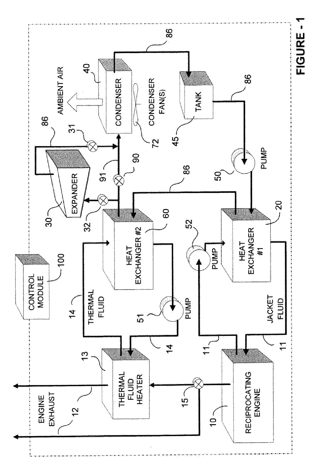
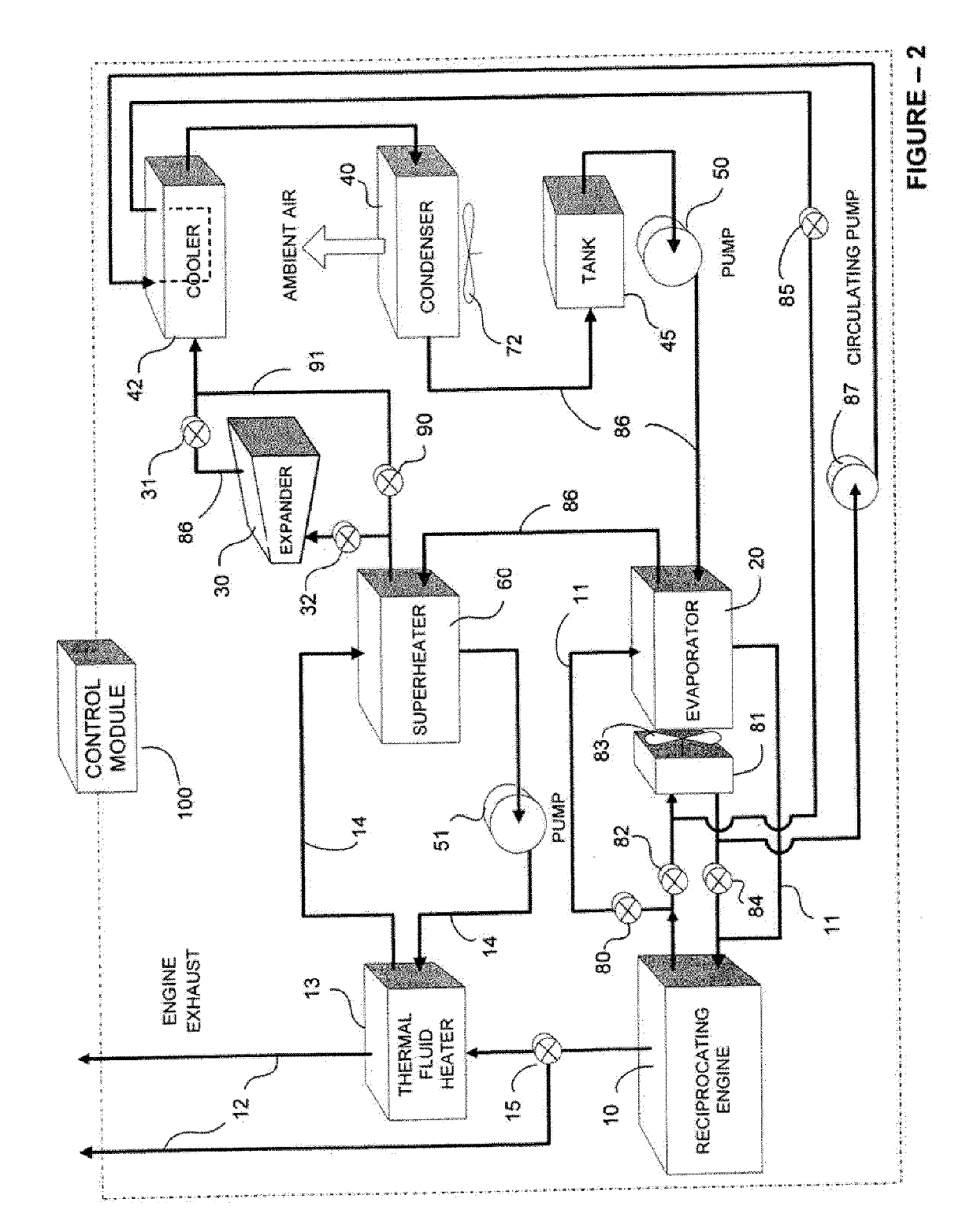
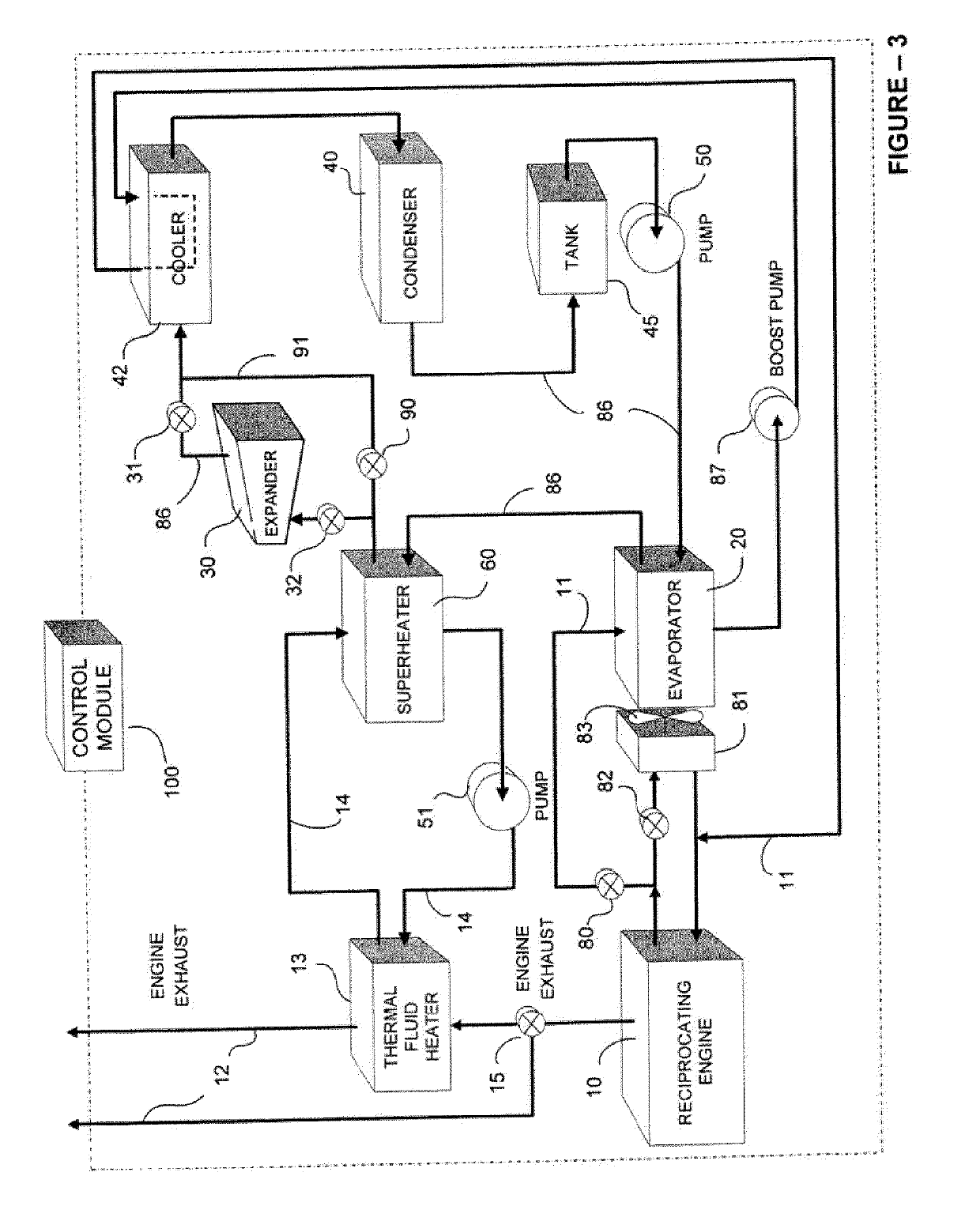
[0013]In a first aspect, there is provided a system for collection and conversion of thermal energy to mechanical energy, the system comprising: a reciprocating engine operable to provide a primary power source and a first source of thermal energy; a circulating pump, at least one propellant heat exchanger, an expander, and a condenser, arranged to operate an Organic Rankine Cycle (ORC) in which thermal energy from said first source of thermal energy is transferred to a liquid organic propellant in the propellant heat exchanger to evaporate the propellant, which expansion of gaseous propellant then drives the expander in production of mechanical energy to create secondary power, with spent propellant from the expander condensed back into liquid form by the condenser for recirculation to the heat exchanger; a cooler comprising a cooling fluid circulating through a supplementary heat exchanger, the supplementary heat exchanger operatively located within the ORC system between the expander and the condenser to provide supplementary propellant cooling capacity; and a control module for regulating operation of the Rankine cycle and supplementary cooler to maximize secondary power generation.
[0020]In any embodiment, thermal energy may be transferred directly or indirectly to propellant within the ORC. For example, thermal energy from a second source of thermal energy may be first transferred to an intermediate fluid, which transfers thermal energy to the propellant. When the first source of thermal energy is engine jacket fluid, thermal energy from the second source may be transferred to the engine jacket fluid to further increase the thermal energy content of the jacket fluid prior to the engine jacket fluid circulating to the propellant heat exchanger.
[0024]In a further aspect, there is provided a system for collection and conversion of thermal energy to mechanical energy, the system comprising: a natural gas compressor operable to compress natural gas within natural gas conduits, the natural gas compressor providing a first source of thermal energy; a circulating pump, one or more heat exchangers, an expander, and a condenser, arranged to operate an ORC in which thermal energy is transferred directly or indirectly to a liquid organic propellant using the one or more heat exchangers to evaporate the propellant, which gaseous propellant then drives the expander in production of mechanical energy to create secondary power, with spent propellant from the expander condensed back into liquid form by the condenser for recirculation to the heat exchanger; and a control module for regulating operation of the Rankine cycle to maximize secondary power generation.
[0037]In another aspect, there is provided a method for heating propellant within an ORC system, the ORC system associated with a natural gas compressor powered by a reciprocating engine, the method comprising the steps of: collecting waste thermal energy from the reciprocating engine within a heat transfer fluid; collecting waste thermal energy from the natural gas compressor by circulation of compressor lubricating fluid about the compressor; circulating each of the heat transfer fluid and compressor lubricating fluid to one or more heat exchangers to facilitate direct or indirect transfer of engine and compressor thermal energy to propellant circulating within the ORC.

Problems solved by technology

Although specialized organic propellants having high flash temperatures (for example Genetron® R-245fa, which is 1,1,1,3,3-pentafluoropropane) have been developed, the danger of combustibility still exists, as engine exhaust may reach temperatures up to 1200 degrees F. Further, the purchase of proprietary propellants adds a significant cost to these systems and requires the ORC system to be in close proximity to the heat source.
A common problem particularly relevant to recovery of thermal energy is that when using air-cooled condensers, ambient air temperatures significantly impact the ORC system efficiency and total power generated.
Retrofitted systems for recovering heat from a reciprocating engine are generally limited by pre-existing space constraints and site conditions, particularly when used in remote locations.
Generally, heat recovery systems of the prior art require close proximity to the engine, liquid condensing, expensive components, do not incorporate a recuperator (economizer) and are not sufficiently adaptable to recover and utilize thermal energy from other sources, if present.

Method used


Image

  • Supplementary Thermal Energy Transfer in Thermal Energy Recovery Systems
  • Supplementary Thermal Energy Transfer in Thermal Energy Recovery Systems
  • Supplementary Thermal Energy Transfer in Thermal Energy Recovery Systems

Examples


Embodiment Construction

[0064]Generally, the present invention provides a method and system to recover and dissipate thermal energy from a reciprocating engine and / or a natural gas compressor, through controlled operation of an ORC system to produce secondary power. Various configurations are provided to maximize efficiency of the Rankine cycle and secondary energy output in various applications. With improvements in efficiency and increased generation of secondary power, system resources may be further allocated to heating and / or cooling the organic propellant, allowing for more efficient operation of the ORC system and / or increased secondary power generation.

[0065]Generally, an ORC system is provided in which thermal energy is collected from a reciprocating engine and / or a natural gas compressor, and used to produce secondary power. Accordingly, thermal energy may be collected from one or more of the following sources and transferred to propellant: engine jacket fluid, engine auxiliary cooling fluid, eng...


PUM


Abstract

A system for controlled recovery of thermal energy and conversion to mechanical energy. The system collects thermal energy from a reciprocating engine (for example, from engine jacket fluid) and may also collect further thermal energy from a natural gas compressor (for example, from compressor lubricating fluid). The collected thermal energy is used to generate secondary power by evaporating an organic propellant and using the gaseous propellant to drive an expander in production of mechanical energy. Secondary power is used to power parasitic loads, improving energy efficiency of the system. A supplementary cooler may provide additional cooling capacity without compromising system energy efficiency.

Description

[0001]This application is a continuation-in-part of PCT / CA2008 / 000402 filed Mar. 3, 2008. This application claims the benefit Canadian Application No.: (not yet assigned) filed Aug. 24, 2009. These applications are hereby incorporated by reference.BACKGROUND OF THE INVENTION[0002]The present invention relates generally to thermal energy recovery systems. More particularly, the present invention relates to the efficient, controlled operation of an Organic Rankine Cycle (ORC) system in which waste heat is recovered from a reciprocating engine and / or a natural gas compressor coupled to a reciprocating engine.[0003]Methods for implementing a Rankine cycle within a system to recover thermal energy from a heat source are well known. Although most waste heat recovery systems were initially developed to produce steam that could be used to drive a steam turbine, the basic principles of the Rankine cycle have since been extended to lower temperature applications by the use of organic propella...

Claims


Application Information

Patent Timeline
IPC IPC(8): F01K25/08F01K13/02
CPCF01K23/065F01K23/02F01K25/10
Inventor JUCHYMENKO, VICTOR
Owner JUCHYMENKO VICTOR
Learn More