Sorbent Filter for the Removal of Vapor Phase Contaminants

a technology of sorbent filters and vapor phase contaminants, which is applied in the direction of dispersed particle separation, separation processes, transportation and packaging, etc., can solve the problems of mercury contamination of the bed, difficulty in removing volatile compounds, and special design and costly emissions control systems. to effectively capture these trace amounts of mercury

Inactive Publication Date: 2009-12-31
ELECTRIC POWER RES INST INC
View PDF77 Cites 79 Cited by
  • Summary
  • Abstract
  • Description
  • Claims
  • Application Information

AI Technical Summary

Problems solved by technology

For example, mercury is present in flue gas from a fossil-fuel-fired combustion system in very low concentrations (<1 ppb) and forms a number of volatile compounds that are difficult to remove.
Specially designed and costly emissions-control systems are required to effectively capture these trace amounts of mercury.
However, in regenerating the sorbent in such fixed bed systems, the bed must be taken off-line periodically.
These fixed bed systems also require significant space since they need to remove vapor phase contaminants, such as mercury, for long periods of time without having to be replaced or regenerated, and they are very difficult to retrofit into existing systems, such as into the ductwork of power plants, without major modifications and high pressure drop penalties (e.g., 10-30 inches of water).
However, the fabrication of porous tubes and plates is complex and relatively expensive.
The tubes and plates are also heavy and difficult to install and heat due to the thick wall requirements.

Method used


Image

  • Sorbent Filter for the Removal of Vapor Phase Contaminants
  • Sorbent Filter for the Removal of Vapor Phase Contaminants
  • Sorbent Filter for the Removal of Vapor Phase Contaminants

Examples


Embodiment Construction

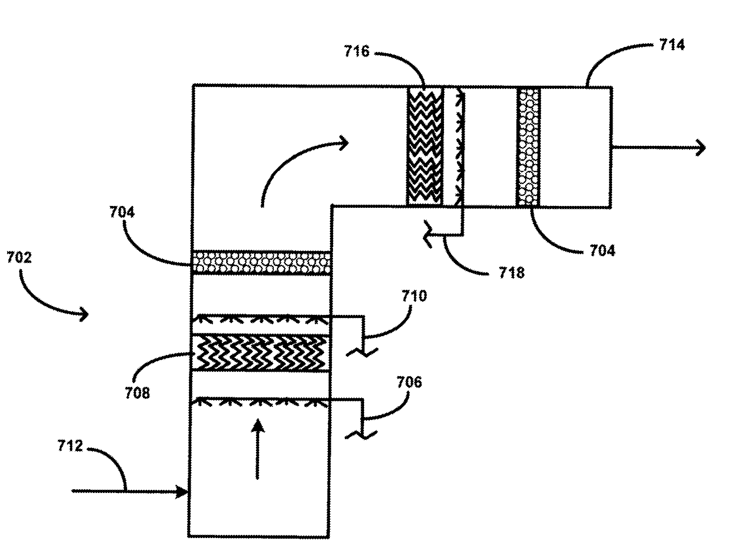
[0022]Generally, the invention comprises methods and apparatuses for removing a contaminant from a gas stream, such as vaporous trace metal contaminants. In one embodiment, a primary particulate collection device that removes particulate matter is used. In this embodiment, a sorbent filter is placed within the housing of the primary particulate collection device, such as an electrostatic precipitator or a baghouse, to adsorb the contaminant of interest. In another embodiment, a sorbent filter is placed within a scrubber, such as a wet scrubber, to adsorb the contaminant of interest. In some embodiments, the invention provides methods and apparatuses that can advantageously be retrofit into existing particulate collection equipment. In some embodiments, the invention provides methods and apparatuses that in addition to removal of a vapor phase contaminant additionally remove particulate matter from a gas stream.

[0023]The following describes these and other exemplary embodiments of th...


PUM

PropertyMeasurementUnit
diameteraaaaaaaaaa
sizeaaaaaaaaaa
concentrationsaaaaaaaaaa

Abstract

Methods and apparatuses are described for removing a contaminant, such as a vaporous trace metal contaminant like mercury, from a gas stream. In one embodiment, a primary particulate collection device that removes particulate matter is used. In this embodiment, a sorbent filter is placed within the housing of the primary particulate collection device, such as an electrostatic precipitator or a baghouse, to adsorb the contaminant of interest. In another embodiment, a sorbent filter is placed within or after a scrubber, such as a wet scrubber, to adsorb the contaminant of interest. In some embodiments, the invention provides methods and apparatuses that can advantageously be retrofit into existing particulate collection equipment. In some embodiments, the invention provides methods and apparatuses that in addition to removal of a contaminant additionally remove particulate matter from a gas stream.

Description

[0001]This application is a continuation-in-part application of application Ser. No. 11 / 592,606, filed Nov. 3, 2006, the entirety of which is hereby incorporated by reference herein.BACKGROUND[0002]1. Background of the Invention[0003]The invention relates generally to the removal of vapor phase contaminants from a gas stream. More specifically, the invention is directed to a method and apparatus for the removal of vapor phase contaminants, such as mercury, from the flue gas of a combustion system.[0004]2. Description of Related Art[0005]The emission of trace metals from utility power plants is an important concern. In particular, special attention has been given to trace contaminants, including, for example, mercury (Hg), in terms of their release into the environment and corresponding impacts on the environment. Generally, trace contaminants include those vaporous chemical species present in relatively low concentrations in a given gas stream as well as solid particulate matter. Fo...

Claims


Application Information

Patent Timeline
Patent Type & Authority Applications(United States)
IPC IPC(8): B01D50/00B01D53/02B01D53/46B01D47/00
CPCB01D46/002B03C3/155B01D46/0032B01D46/0036B01D46/02B01D46/521B01D47/06B01D50/006B01D53/04B01D53/64B01D2253/10B01D2253/102B01D2257/2042B01D2257/2045B01D2257/2047B01D2257/2064B01D2257/302B01D2257/60B01D2257/602B01D2257/70B01D2267/40B03C3/09B01D46/0023B01D53/08B01D46/58B01D46/62B01D50/60
Inventor CHANG, RAMSAYDENE, CHARLES E.MONROE, LARRY SCOTBERRY, MARK SIMPSONLOONEY, M. BRANDON
Owner ELECTRIC POWER RES INST INC
Why Eureka
Try Eureka