Structure for mounting batteries in guideway electric vehicle

a technology for electric vehicles and structures, applied in the direction of locomotive propulsion types, propulsion parts, electric devices, etc., can solve the problems of increased vehicle weight, deteriorated running stability, and the battery room cannot be sealed from the car room, so as to increase the safety of passengers, prolong the use life of the battery module, and increase the cooling effect of the battery

Active Publication Date: 2009-12-31
MITSUBISHI HEAVY IND ENG LTD
View PDF7 Cites 68 Cited by
  • Summary
  • Abstract
  • Description
  • Claims
  • Application Information

AI Technical Summary

Benefits of technology

[0031]By this, the battery module is cooled based on battery temperature, battery room temperature, and outside air temperature so that the batteries operates in as more proper temperature circumstance as possible, as a result usage life of the battery module can be elongated.
[0032]It is preferable that the batteries are arranged vertically in the battery room so that vertical circulation of air occurs in the battery room. With this arrangement of batt

Problems solved by technology

With the prior art of the patent literature 1, it is necessary to increase mechanical strength of the vehicle body including the roof 03 because heavy batteries are mounted on the roof 03, which induces a problem of increased vehicle weight.
Further, height of center of gravity of the vehicle increases by mounting the batteries on the roof 03, resulting deteriorated running stability.
With the prior art of the patent literature 2, air in the car room is taken in from the rear opening 013 to be used to cool the batteries 010, therefore battery room can not be sealed from the car room, and there is fear that the car room is subjected to the influence of battery electrolyte and inflammable gas developed from the battery electrolyte.
Further,

Method used


Image

  • Structure for mounting batteries in guideway electric vehicle
  • Structure for mounting batteries in guideway electric vehicle
  • Structure for mounting batteries in guideway electric vehicle

Examples


first embodiment

The First Embodiment

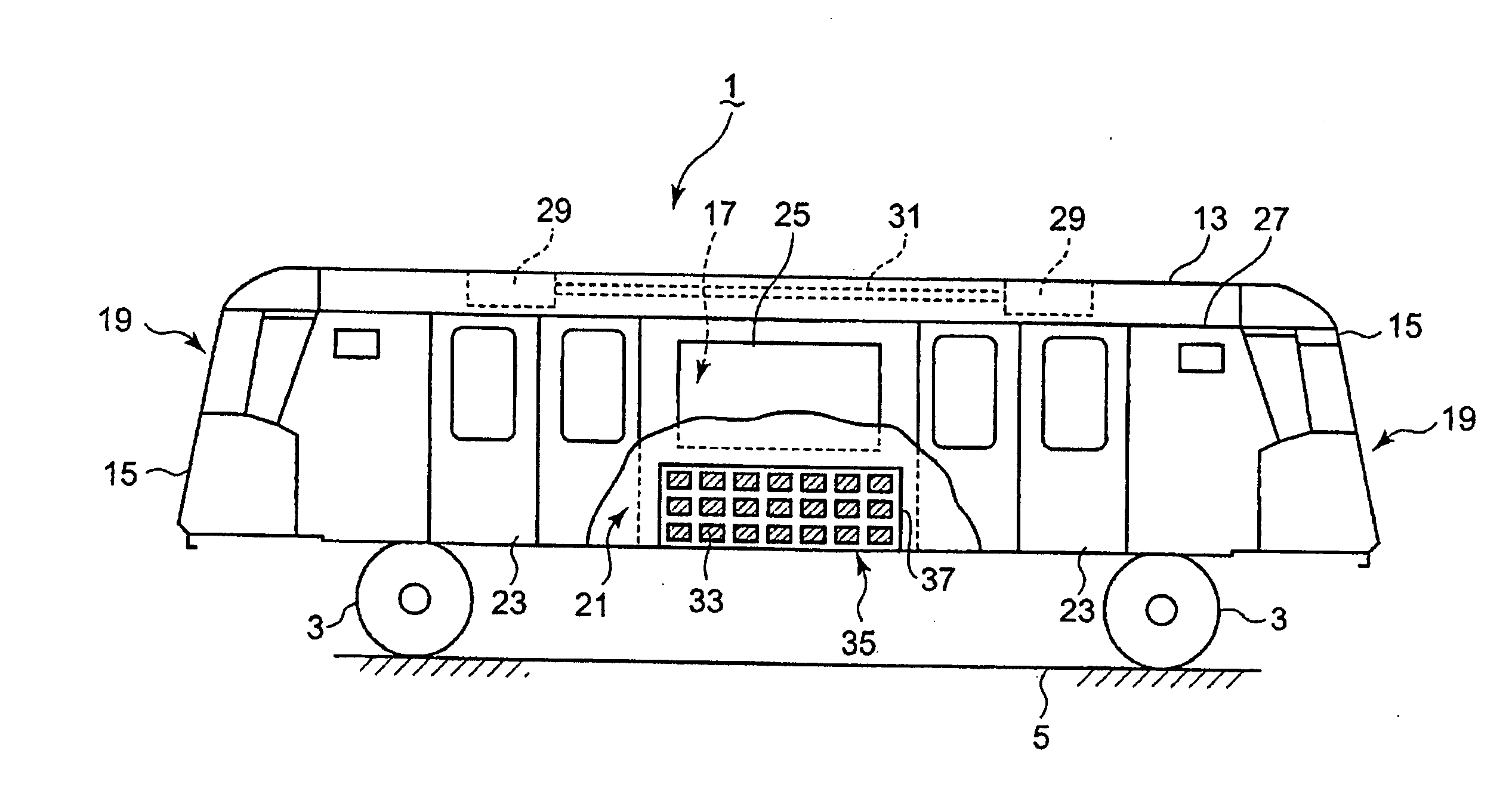
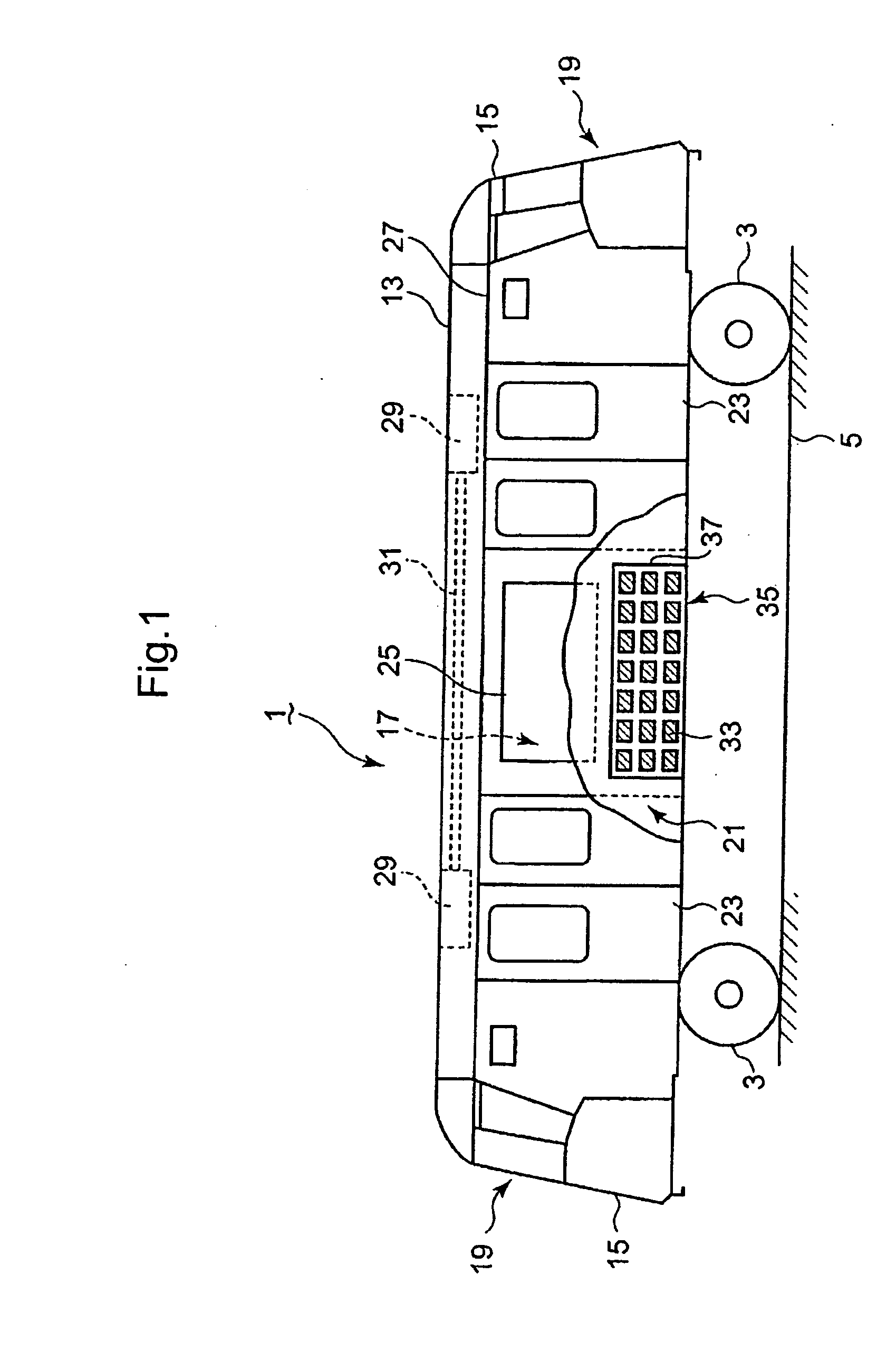
[0057]A first embodiment of the invention will be explained referring to FIGS. 1, 2, 3, 4A, and 4B. As an example, a guideway electric vehicle 1 used for transportation in air ports will be explained. Referring to FIG. 1, the vehicle 1 is an electric vehicle driven by electric power supplied from batteries 33. The vehicle 1 has four rubber-tired wheels 3 and runs along a guideway (roadway 5 in the embodiment).

[0058]As shown in FIGS. 1 and 2, an vehicle interior space 17 is formed by a floor 9, side walls 11, roof 13 and front and rear end walls 15. The vehicle interior space 17 is partitioned into a passenger cabin 21 and driver's cabins 19 (when the vehicle 1 is a manual driven vehicle) at the front and rear end parts of the interior space 17. Two slide doors 23 for passengers getting on and off are provided in the front and rear sides of the passenger cabin 21 and a window 25 are provided in the central part.

[0059]Air conditioners 29 are installed between the r...

second embodiment

The Second Embodiment

[0074]Next, a second embodiment of the invention will be explained with reference to FIGS. 5A, 5B, and 5C.

[0075]In this embodiment, the number of batteries is increased to two rows in width direction of the vehicle and a battery control device 44 is provided in the battery room 35. This is different from the first embodiment. Other than this is the same to the first embodiment and the same reference numerals are used for parts the same to those of the first embodiment and explanation is omitted.

[0076]As the total number of batteries 33 can be increased, life of batteries 33 until recharging can be elongated.

[0077]Further, the battery module 33 can be controlled by the battery control device 44 so that, when the battery module is in an abnormal state, for example in a state that temperature of the batteries (temperature of the battery electrolyte) is higher than the standard temperature, that electric current or voltage shows that the batteries are in overload or...

third embodiment

The Third Embodiment

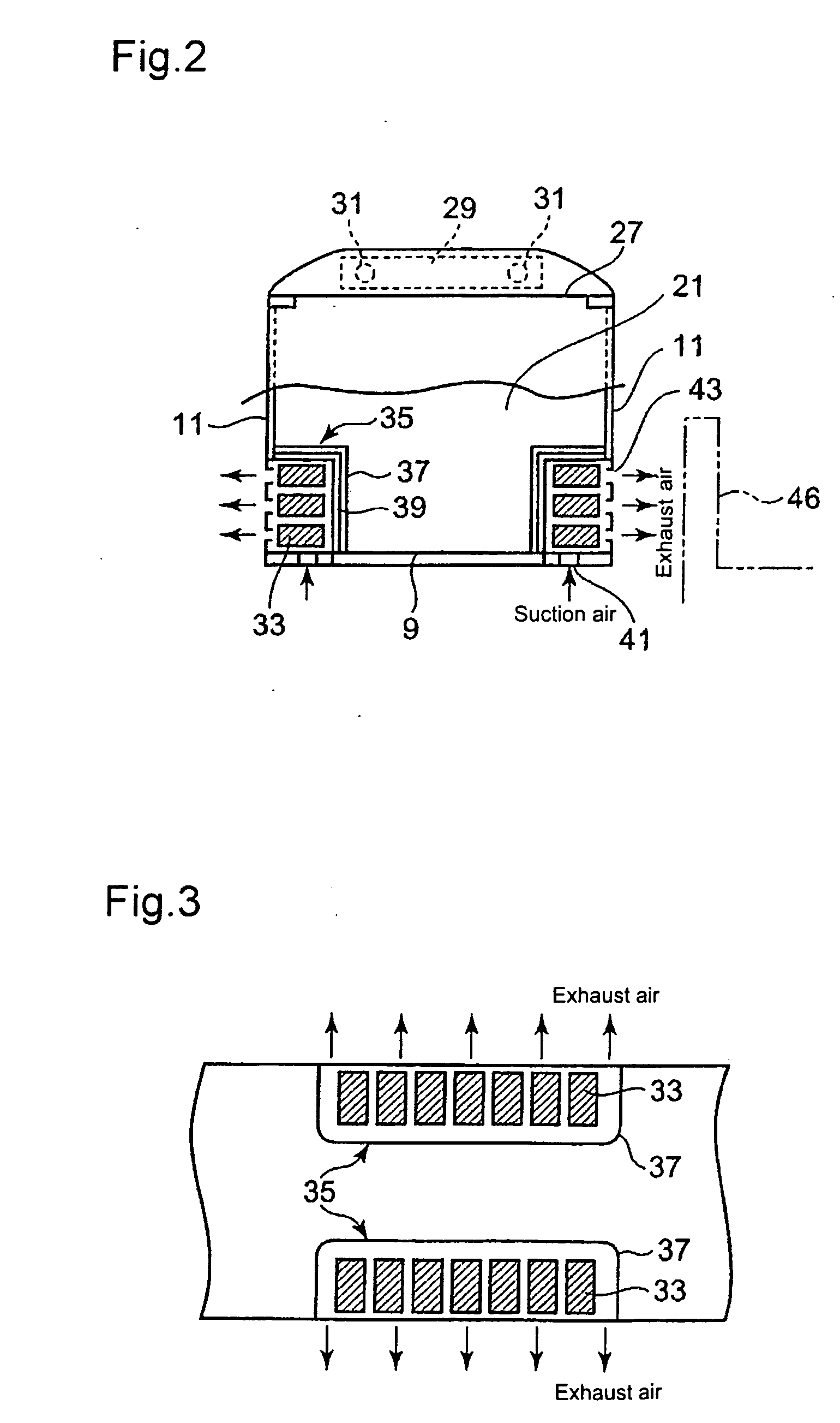
[0079]A third embodiment of the invention will be explained referring to FIG. 6. In this third embodiment, suction openings 41 for taking in outside air to the battery room 35 and exhaust openings 43 for letting out heated air to the outside of the vehicle are formed in the side wall 11, different from the first embodiment in which the suction openings 41 are formed in the floor 9 and the exhaust openings 43 are formed in the side wall 11.

[0080]As the suction openings 41 are provided in the side wall 11 without being interrupted partly by devices and cables located under the floor 9 as may be when the suction openings 41 are provided in the floor 9, design freedom of determining location of the suction openings 41 and exhaust openings 43 can be increased and the openings 41, 43 can be located so that cooling effect of the battery module 33 in the battery room 35 is increased.

[0081]It is also suitable to provide the suction openings 41 and exhaust openings 43 in t...


PUM


Abstract

Structure for mounting batteries in a guideway electric vehicle driven by a battery-driven motor is provided, with which balancing in weight of the vehicle is properly achieved, batteries can be cooled enough, battery rooms are completely sealed from the passenger room, and running stability of the vehicle is ensured.
The battery mounting structure is composed such that battery rooms (35) for mounting battery modules (33) comprised of a plurality of batteries are formed on a floor (9) of the vehicle in both sides adjacent side walls (11) of the vehicle respectively, each of the battery rooms (35) being partitioned from the passenger cabin of the vehicle hermetically by a partition plate (37); suction openings (41) for introducing outside air into the battery room (35) are provided in the floor (9) or side wall (11) of the vehicle in each battery room (35), and exhaust openings (41) for releasing air to the outside of the vehicle are provided in the side wall (11) thereof in each battery room (35); whereby the battery module (33) in each battery room (35) can be cooled by outside air.

Description

TECHNICAL FIELD[0001]The present invention relates to structure for mounting batteries for supplying electric power to an electric motor in a guideway electric vehicle which runs on guide ways such as tramways, elevated guide ways, exclusive railroads, and so on.BACKGROUND ART[0002]Electric vehicles driven by electric power supplied from a battery unit have prevailed in recent years. The battery is heavy in weight and cooling thereof is necessary, and place and structure for mounting batteries in the vehicles have been studied and proposed.[0003]Conventionally, electric power is supplied to the vehicles via an overhead wire provided along the guideway. However, in a new transit system in which electric vehicles with rubber-tired wheels run on guide ways provided with guide rails, a power supply system without overhead wire is demanded from the viewpoint of simplification of the power supply system, and in the case of battery driven electric vehicle, improvement concerning structure ...

Claims


Application Information

Patent Timeline
IPC IPC(8): B60R16/04B60L50/64
CPCB60K1/04B60L2200/26B60K2001/0438B60K2001/0472B60L3/0046B60L11/1874B60Y2200/143B60Y2200/30B60Y2200/91B60Y2200/912B61C3/02B61C17/06H01M2/1077H01M2/1083H01M10/5004H01M10/5016H01M10/502H01M10/5024H01M10/5038H01M10/5067H01M10/5073H01M10/5087H01M10/5095Y02T10/7005Y02T10/7055Y02T30/12Y02T30/18B60K2001/005H01M10/625H01M10/63H01M10/663H01M10/6563H01M10/652H01M10/635H01M10/6566H01M10/613H01M10/658B60L1/003B60L1/02B60L2200/18B60L2200/30B60L2200/36B60L2240/34B60L2240/545B60L58/26B60L50/66B60L50/64Y02T10/70Y02T30/00Y02E60/10H01M50/249H01M50/244H01M50/289
Inventor MORITA, KATSUAKIMITAKE, MASAYAHOSHI, MITSUAKIKATAHIRA, KOUSUKE
Owner MITSUBISHI HEAVY IND ENG LTD
Why Eureka
Try Eureka