Controlling a Melt-Solid Interface Shape of a Growing Silicon Crystal Using an Unbalanced Magnetic Field and Iso-Rotation

Active Publication Date: 2009-12-31
GLOBALWAFERS CO LTD
View PDF10 Cites 10 Cited by
  • Summary
  • Abstract
  • Description
  • Claims
  • Application Information

AI Technical Summary

Benefits of technology

[0004]Accordingly, improved control of the crystal growth process is desired to control the shape of the

Problems solved by technology

The method includes applying an unbalanced cusped magnetic field to the melt, and rotating th

Method used


Image

  • Controlling a Melt-Solid Interface Shape of a Growing Silicon Crystal Using an Unbalanced Magnetic Field and Iso-Rotation
  • Controlling a Melt-Solid Interface Shape of a Growing Silicon Crystal Using an Unbalanced Magnetic Field and Iso-Rotation
  • Controlling a Melt-Solid Interface Shape of a Growing Silicon Crystal Using an Unbalanced Magnetic Field and Iso-Rotation

Examples


Embodiment Construction

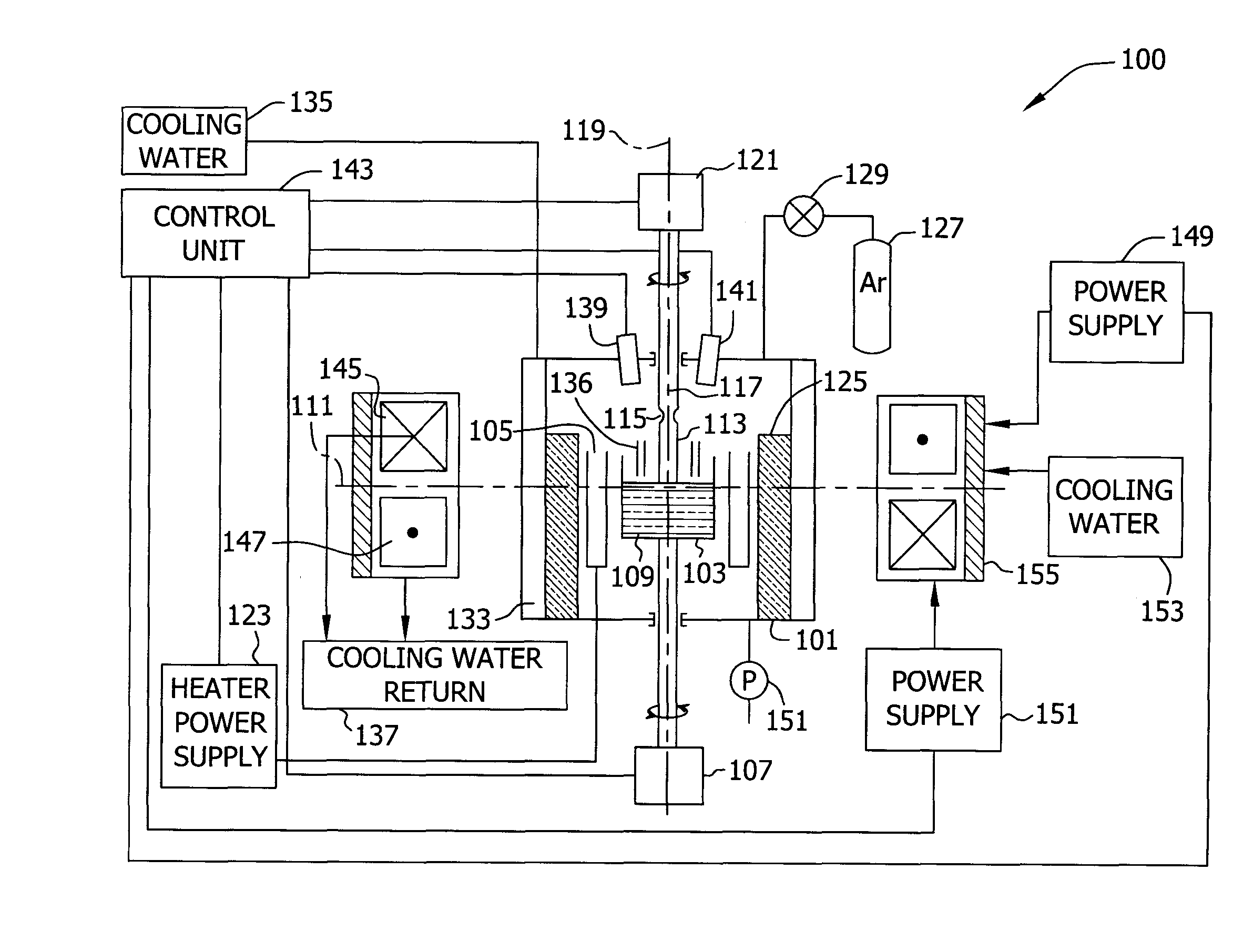
[0019]Controlling a shape of a melt-solid interface is an important factor in determining the quality of silicon crystal produced. The shape of the melt-solid interface is dependent on process parameters such as, but not limited to, temperatures, crucible or crystal rotation, and crystal pulling rate. By fixing these process parameters, the melt-solid interface is also fixed. In an exemplary embodiment, a magnetic field applied during the crystal growing process also affects the shape of the melt-solid interface. Magnetic fields may be used to stabilize convective flows in metal and semiconductor melts and to dampen natural convective flow and turbulence. There are three conventional types of magnetic field configurations used to stabilize convective flows in conductive melts, namely, axial, horizontal, and cusped.

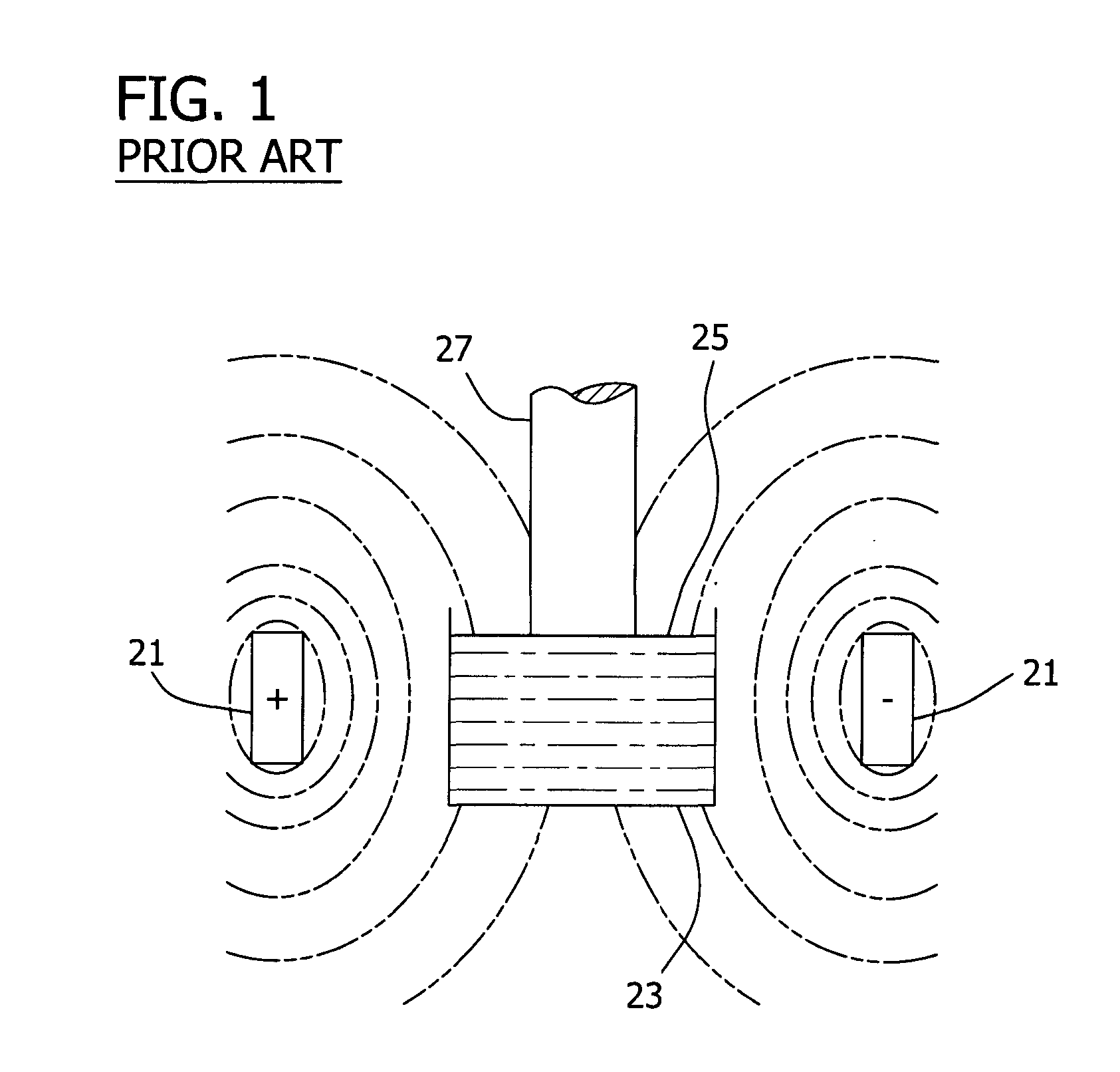
[0020]FIG. 1 is a block diagram illustrating an axial (also referred to herein as vertical) magnetic field being applied to a crucible 23 containing a melt 25 in a crystal...


PUM


Abstract

A system for growing silicon crystals that facilitates controlling a shape of a melt-solid interface is described. The crystal growing system includes a heated crucible including a semiconductor melt from which a monocrystalline ingot is grown according to a Czochralski process. The ingot is grown on a seed crystal pulled from the melt. The method includes applying an unbalanced cusped magnetic field to the melt, and rotating the ingot and the crucible in the same direction while the ingot is being pulled from the melt.

Description

CROSS-REFERENCE TO RELATED APPLICATION[0001]This application claims the benefit of U.S. Provisional Application No. 61 / 077,082, filed Jun. 30, 2008, which is hereby incorporated by reference in its entirety.BACKGROUND[0002]Single crystal silicon, which is the starting material in most processes for fabricating semiconductor electronic components, is commonly prepared according to the so-called Czochralski process. In this process, polycrystalline silicon, or polysilicon, is charged to a crucible and melted, a seed crystal is brought into contact with the molten silicon, and a single crystal (also referred to herein as monocrystalline) ingot is grown by relatively slow extraction. After formation of a neck is complete, decreasing the pulling rate and / or the melt temperature enlarges the diameter of the crystal until a desired or target diameter is reached. The generally cylindrical main body of the crystal, which has an approximately constant diameter, is then grown by controlling th...

Claims


Application Information

Patent Timeline
IPC IPC(8): C30B30/04
CPCC30B15/305Y10T117/1032C30B30/04C30B29/06
Inventor SREEDHARAMURTHY, HARIPRASADKULKARNI, MILIND S.SCHRENKER, RICHARD G.HOLZER, JOSEPH C.KORB, HAROLD W.
Owner GLOBALWAFERS CO LTD
Why Eureka
Try Eureka