Multi-chip module for power supply circuitry

Inactive Publication Date: 2009-12-31
RICHTEK TECH
View PDF2 Cites 16 Cited by
  • Summary
  • Abstract
  • Description
  • Claims
  • Application Information

AI Technical Summary

Benefits of technology

[0019]By eliminating the parasitic elements between the current sensor, the controller, and the power switches, the present invention reduces the converter lo

Problems solved by technology

However, there is no help for minimizing the signal paths

Method used


Image

  • Multi-chip module for power supply circuitry
  • Multi-chip module for power supply circuitry
  • Multi-chip module for power supply circuitry

Examples


Example

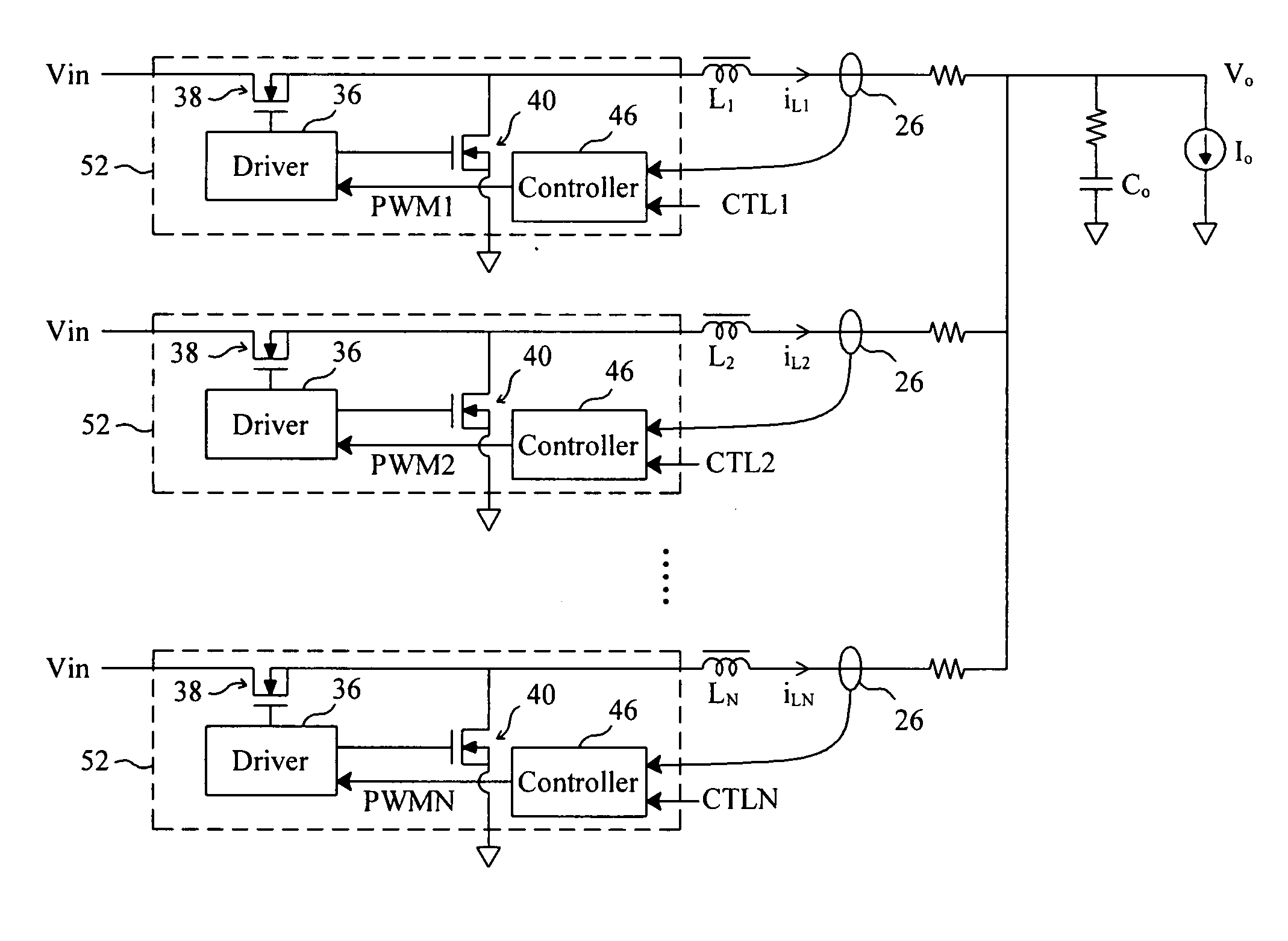
[0030]FIG. 3 shows an embodiment according to the present invention, in which an MCM 32 combines a modulator 34, a driver 36 and two power MOSFETs 38 and 40 in a single chip. The modulator 34 generates an internal PWM signal to the driver 36 according to an external control signal CTL to switch the MOSFETs 38 and 40. The external control signal CTL may include a current signal, a voltage signal and others such as a reference current signal, an output voltage feedback signal, an external PWM signal, and so on, depending on the demands in practical applications. As known in the art, the modulator 34, the driver 36 and the MOSFETs 38 and40 are all bounded on an MCM package substrate (not shown). Based on practical circuit planning, a current sense function may be also integrated in the MCM 32, for example, by incorporating an internal current sensor 42 shown in FIG. 3. In this disclosure, the term “internal” indicates “inside an MCM” while the term “external” indicates “outside an MCM”...


PUM


Abstract

A multi-chip module (MCM) for power supply circuitry integrates a controller, a driver and two power MOSFETs in a single chip to shorten the signal path between the controller and the driver. When applied to a voltage regulator, the MCM shortens the feedback paths between the current sensors and the controller, so as to reduce the loss of and interference with the feedback signals, thereby improving the efficiency of the voltage regulator and simplifying the PCB traces routing.

Description

FIELD OF THE INVENTION[0001]The present invention relates to low-voltage, high-current voltage regulator applications which use multi-channel buck converters. More specifically, the present invention relates to a multi-chip module (MCM) which combines a controller, a driver and two MOSFETs for a multi-channel buck converter to improve response performance during load transient and efficiency.BACKGROUND OF THE INVENTION[0002]The circuitry of low-voltage, high-current voltage regulator applications using multi-channel buck converters has substantial area on printed circuit boards (PCBs). It is agreeable to improve the converter efficiency by reducing the power losses due to the parasitic components present in the layout path and the noise susceptible traces on the PCBs.[0003]Based on the Intel Platform Layout Requirements for CPU power supply, some stages of a multiphase voltage regulator are placed away from the PWM controller as shown in FIG. 1. In this partial layout of a motherboa...

Claims


Application Information

Patent Timeline
IPC IPC(8): G05F1/00
CPCH02M3/1584Y02B70/1466H02M7/003H02M3/1588Y02B70/10
Inventor LI, CHUNG-SHULEE, CHIA-JUNG
Owner RICHTEK TECH
Why Eureka
Try Eureka