Spinal Dynamic Stabilization Rods Having Interior Bumpers

a dynamic stabilization rod and spine technology, applied in the field of spine dynamic stabilization rods having interior bumpers, can solve the problems of limited capping techniques, disadvantageous caps, and further damag

Inactive Publication Date: 2009-12-31
DEPUY SYNTHES PROD INC
View PDF105 Cites 52 Cited by
  • Summary
  • Abstract
  • Description
  • Claims
  • Application Information

AI Technical Summary

Benefits of technology

[0023]In some preferred embodiments, the elastomer component is contained within the rod, thus preventing possible wear debris from entering the body.
[0024]In some preferred embodiments, the elastomer component is contained within the rod within the screw attachment so that the rod can be very short without a central component interfering between the adjacent pedicle screws.
[0025]In some preferred embodiments, the elastomer component is hourglass-shaped to provide programmable stiffness in both compression and extension.

Problems solved by technology

As a result, additional stress may be applied to the adjoining levels, thereby potentially leading to further damage.
Capping techniques, however, are limited in use as they will not remove the source of the pain in osteoarthritic joints.
Caps are also disadvantageous as they must be available in a variety of sizes and shapes to accommodate the wide variability in the anatomical morphology of the facets.
Caps also have a tendency to loosen over time, potentially resulting in additional damage to the joint and / or the bone support structure containing the cap.
One drawback of current articulating facet replacement devices, however, is that they require the facet joints to be resected.
Moreover, alignment of the articulating surfaces with one another can be challenging.
Traditional spine fusion may result in iatrogenic instability at adjacent spine levels and subsequently require additional surgery to fuse more levels.

Method used


Image

  • Spinal Dynamic Stabilization Rods Having Interior Bumpers
  • Spinal Dynamic Stabilization Rods Having Interior Bumpers
  • Spinal Dynamic Stabilization Rods Having Interior Bumpers

Examples


Embodiment Construction

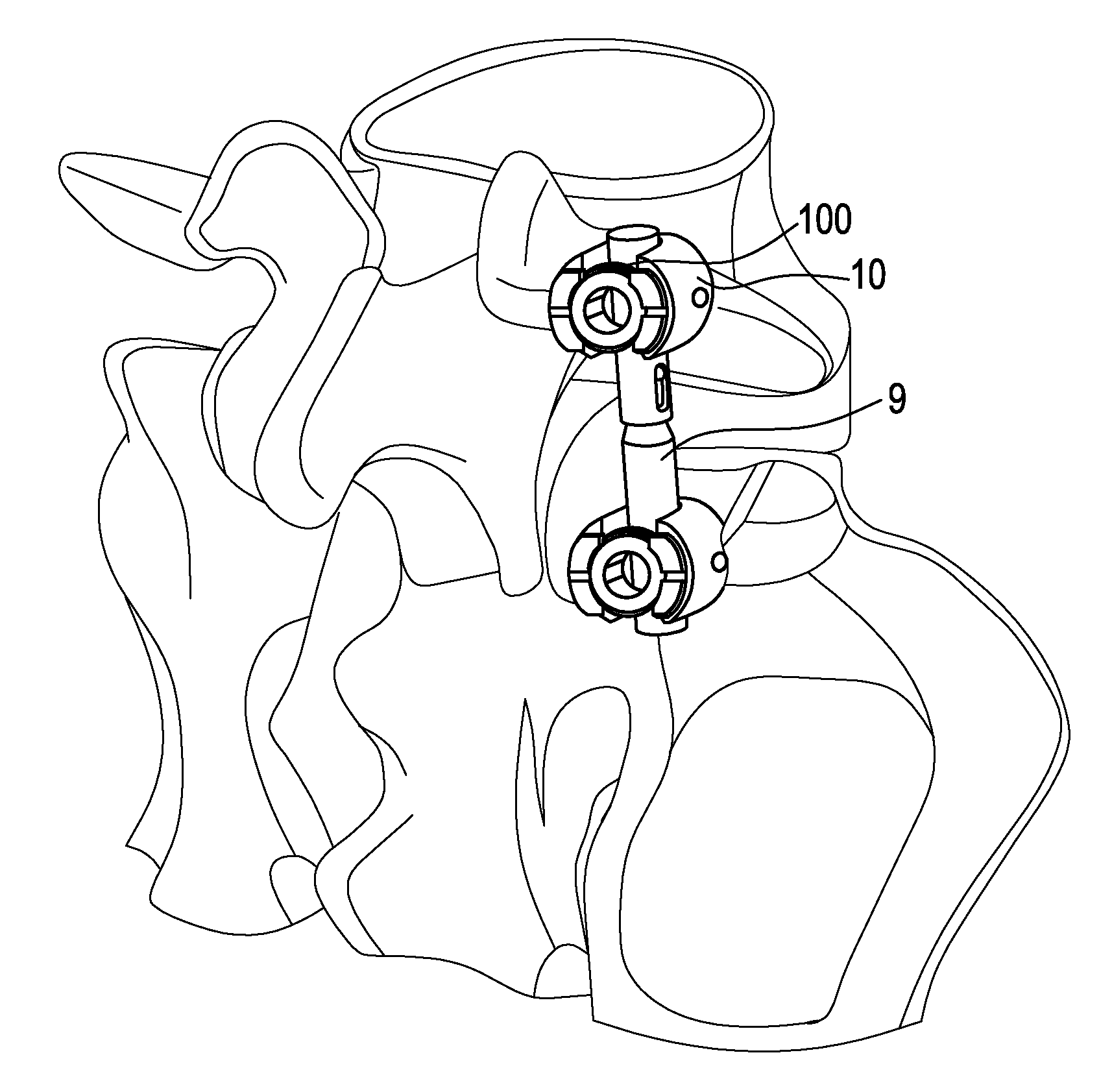
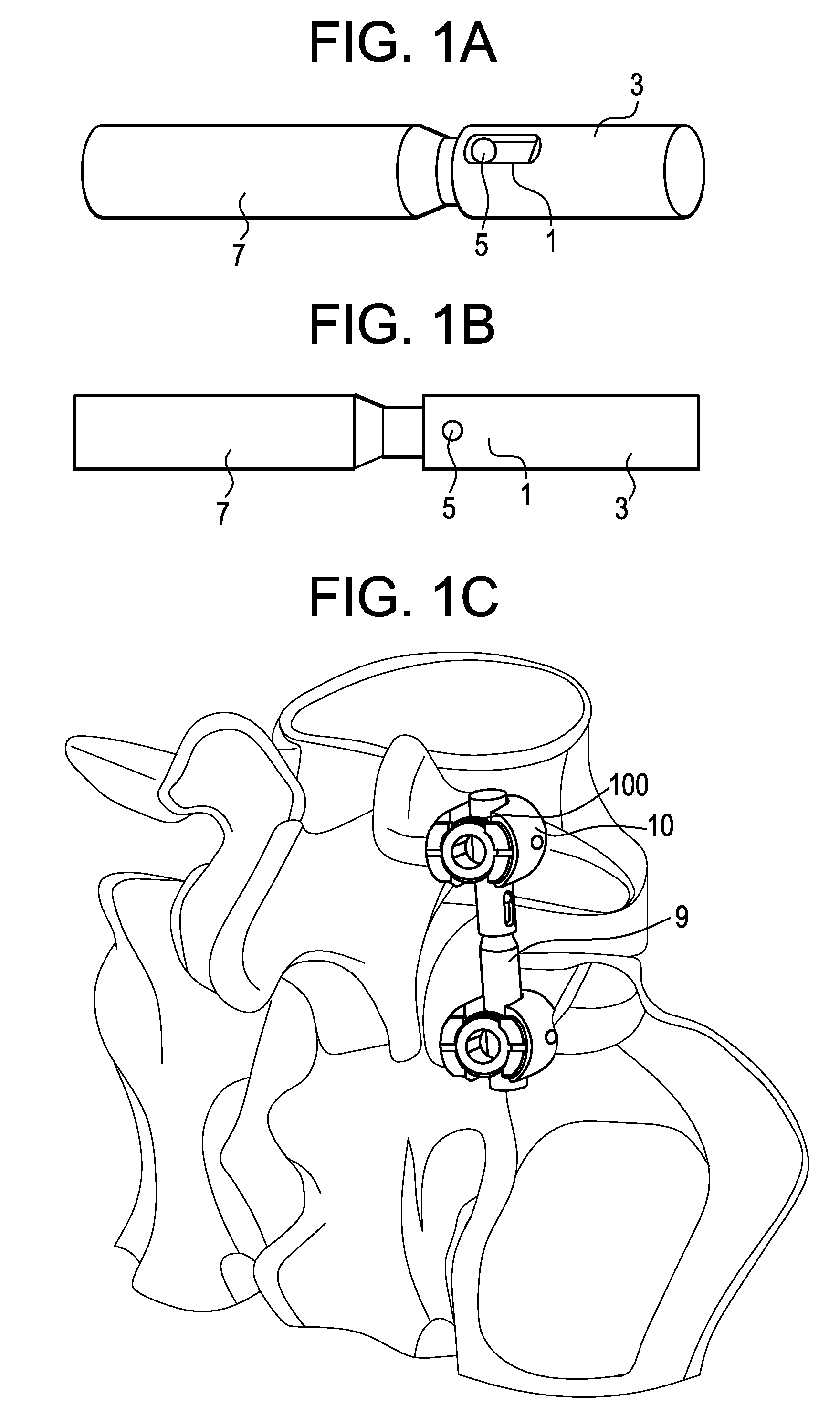
[0039]FIGS. 1a-1b show one embodiment of the hollow cylinder-bumper-rod assembly of the present invention including a) a slot 1 in a hollow cylinder component 3 and b) a pin 5 that is fixed to solid rod component 7 and provides controlled motion. FIG. 1c demonstrates how the device 9 may be connected to pedicle screws anchored in the spine by bone anchors 10.

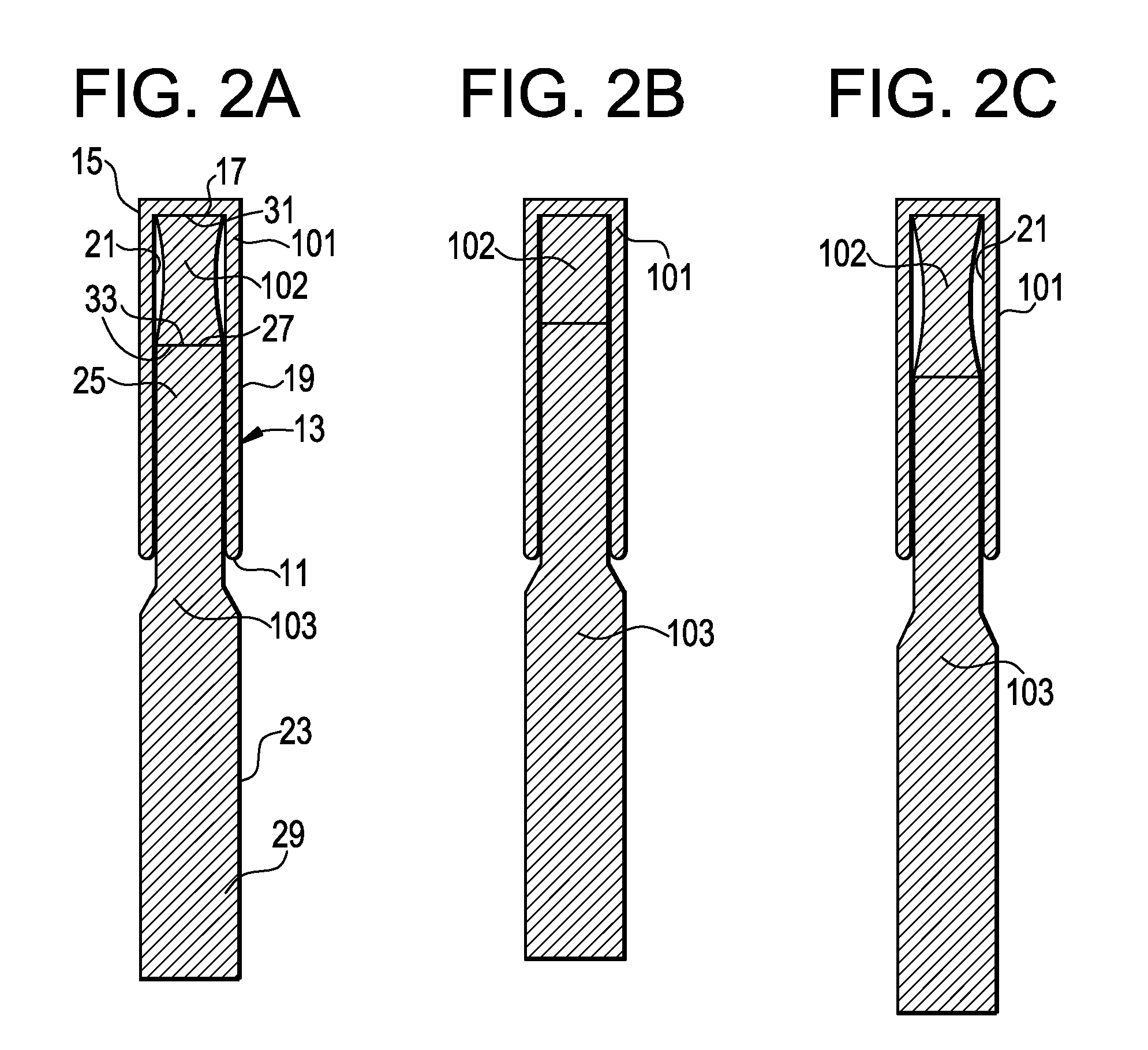
[0040]FIGS. 2a-2c demonstrate movement of the device during compression and extension. Now referring to FIG. 2a, there is provided a device in its unloaded state. The device comprises a polyaxial dynamic stabilization device comprising:[0041]a) a first hollow cylinder 101 having an open end 11, an intermediate annular portion 13 and a closed end 15, the closed end defining an inner surface 17, the intermediate annular portion defining an outer annular surface 19 and a first inner annular surface 21,[0042]b) a first rod 103 having an outer diameter 23, a first end 25 having a first end surface 27, and a second end 29, the first e...


PUM


Abstract

A dynamic stabilization device for use in the human spine, comprising i) a hollow, closed-end cylinder component that is configured for attachment to a first pedicle screw, ii) a solid rod component that is configured on one end to slide freely within the hollow cylinder component, and configured at the other end for attachment to a second pedicle screw and iii) an elastomer component contained within the hollow cylinder and located between the closed end of the hollow cylinder and the end of the solid rod component.

Description

BACKGROUND OF THE INVENTION[0001]The vertebrae in a patient's spinal column are linked to one another by the disc and the facet joints, which control movement of the vertebrae relative to one another. Each vertebra has a pair of articulating surfaces located on the left side, and a pair of articulating surfaces located on the right side, and each pair includes a superior articular surface, which faces upward, and an inferior articular surface, which faces downward. Together the superior and inferior articular surfaces of adjacent vertebra form a facet joint. Facet joints are synovial joints, which means that each joint is surrounded by a capsule of connective tissue and produces a fluid to nourish and lubricate the joint. The joint surfaces are coated with cartilage allowing the joints to move or articulate relative to one another.[0002]Diseased, degenerated, impaired, or otherwise painful facet joints and / or discs can require surgery to restore function to the three joint complex. ...

Claims


Application Information

Patent Timeline
Patent Type & Authority Applications(United States)
IPC IPC(8): A61B17/70
CPCA61B17/7031A61B17/7025
Inventor SLIVKA, MICHAEL ANDREWBURGESS, IAN C.GRINBERG, ALEXANDER
Owner DEPUY SYNTHES PROD INC
Why Eureka
Try Eureka