Percutaneous spinal rod insertion system and related methods

a spinal cord and rod inserting technology, applied in the field of surgical devices, can solve the problems of increased risk of complications, increased invasiveness to patients, and difficulty for surgeons to properly align the end of the curved arm of the rod inserter with the screw head, and achieve the effect of enhancing flexibility

Inactive Publication Date: 2009-12-31
DUARTE LUIS E
View PDF17 Cites 91 Cited by
  • Summary
  • Abstract
  • Description
  • Claims
  • Application Information

AI Technical Summary

Benefits of technology

[0008]It is therefore an object of the present invention to provide a spinal rod implantation system and related methods which allows a surgeon enhanced flexibility when positioning a spinal rod.

Problems solved by technology

Despite the advantages of the Sextant™ system, in some cases it may be difficult for the surgeon to properly align the end of the curved arm of the rod inserter with the screw heads.
If the surgeon is ultimately unable to make the proper alignment after repeated attempts, the surgeon has to resort to a traditional surgical approach, which is more invasive to the patient.
As a result, the patient is required to be under anesthesia for a longer duration, leading to increased risk of complications and a more difficult recovery.

Method used


Image

  • Percutaneous spinal rod insertion system and related methods
  • Percutaneous spinal rod insertion system and related methods
  • Percutaneous spinal rod insertion system and related methods

Examples


Embodiment Construction

[0026]The present description is made with reference to the accompanying drawings, in which preferred embodiments are shown. However, many different embodiments may be used, and thus the description should not be construed as limited to the embodiments set forth herein. Rather, these embodiments are provided so that this disclosure will be thorough and complete. Like numbers refer to like elements throughout, and prime notation is used to indicate similar elements in alternative embodiments.

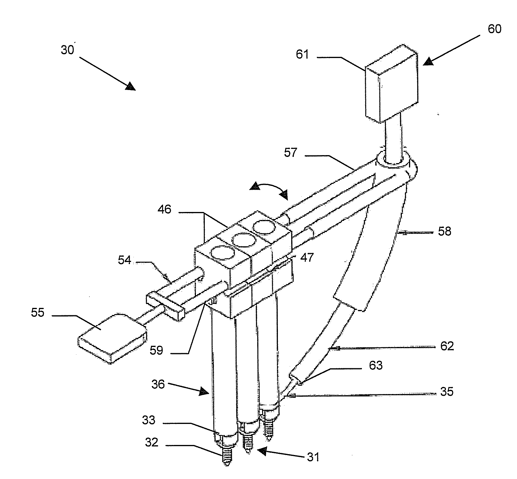
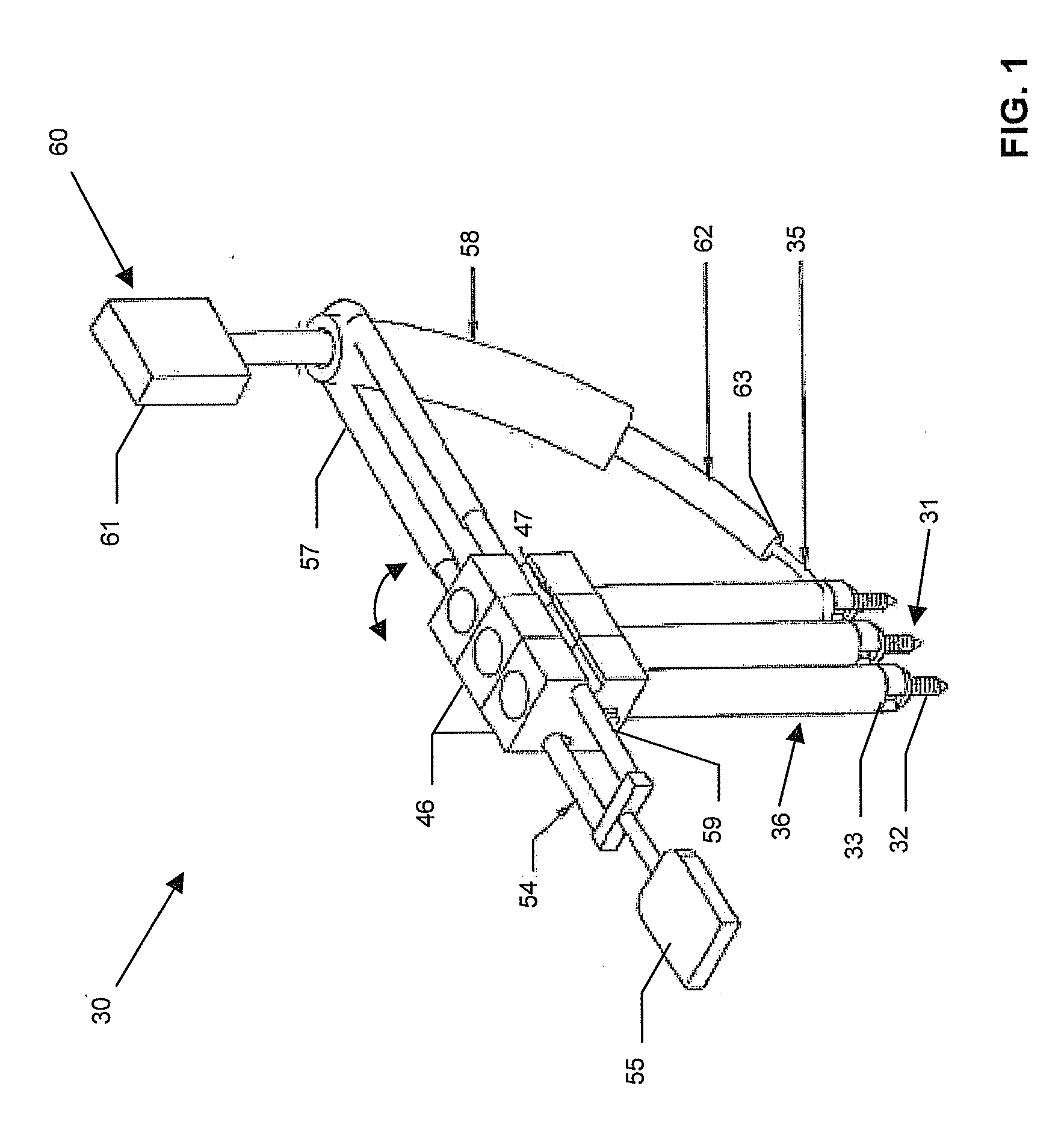
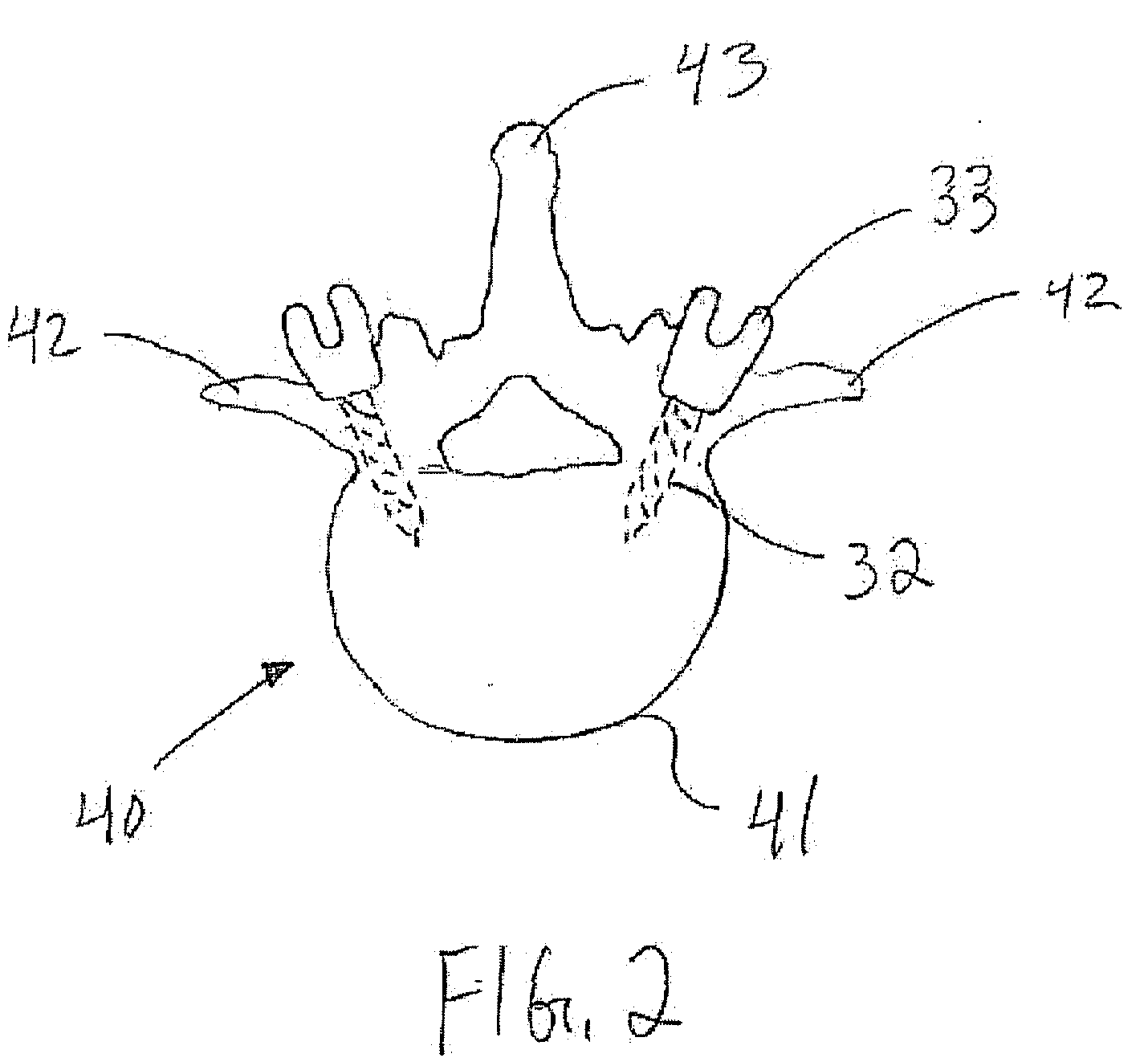
[0027]Referring now to FIGS. 1-9B, a spinal rod insertion system 30 illustratively includes pedicle screws 31, each including a threaded shaft 32 and a pedicle screw head 33 carried by the shaft. Each pedicle screw head 33 has a spinal rod channel or passageway 34 therethrough (see FIG. 8) for receiving a spinal rod 35 therein, which is secured to the pedicle screw head. The spinal rod 35 thus interconnects the pedicle screw heads 33, and the pedicle screws 31 and spinal rod remain in the patient...


PUM


Abstract

A spinal rod implantation system may be used with pedicle screws to be secured to respective pedicles of a patient's spine, each pedicle screw having a spinal rod channel therethrough. The system may include extenders each including an inner member having a distal end, and an outer member surrounding the inner member and being slidable relative thereto to permit removable coupling of the distal end to a respective pedicle screw. The inner and outer members may include respective features defining a first joint permitting at least partial relative rotation to provide a first degree of rotational freedom. The system may further include extender heads each pivotally coupled to a proximal end of a respective outer member to define a second joint providing a second degree of rotational freedom. A spinal rod insertion assembly may be coupled to the extender heads for guiding the spinal rod through the spinal rod channels.

Description

RELATED APPLICATION[0001]This application is based upon prior filed co-pending provisional application Ser. No. 61 / 076,747 filed Jun. 30, 2008, the entire subject matter of which is incorporated herein by reference in its entirety.FIELD OF THE INVENTION[0002]The present invention relates to surgical devices, and, more particularly, to devices for musculoskeletal surgery, such as spinal surgery, and related methods.BACKGROUND OF THE INVENTION[0003]Spinal implant devices and systems are commonly used to correct or stabilize the position of vertebral segments in a patient's back. Such correction may be necessary as a result of accidents, degenerative diseases, etc.[0004]One exemplary spinal implantation system is the CD Horizon® Sextant™ spinal system from Medtronic, Inc. of Minneapolis, Minn., which allows surgeons to deliver and apply screw and rod implants to the posterior aspect of the spine to promote spinal fusion. As discussed in the fact sheet for the Sextant™ system available ...

Claims


Application Information

Patent Timeline
Patent Type & Authority Applications(United States)
IPC IPC(8): A61B17/70A61B17/58A61B17/88
CPCA61B17/7011A61B17/7089A61B17/7032
Inventor DUARTE, LUIS E.
Owner DUARTE LUIS E
Why Eureka
Try Eureka