Fuel injection device

a fuel injection device and fuel injection technology, applied in the direction of electrical control, process and machine control, instruments, etc., can solve the problems of inability to accurately control the fuel injection amount of the latter fuel injection, the limitation of forming the smallest diameter part of the venturi constriction, and the difficulty in smoothly and rapidly drawing the venturi constriction in terms of tube drawing technique, etc., to achieve accurate calculation of the fuel injection amount

Inactive Publication Date: 2009-12-31
HONDA MOTOR CO LTD
View PDF7 Cites 80 Cited by
  • Summary
  • Abstract
  • Description
  • Claims
  • Application Information

AI Technical Summary

Benefits of technology

[0017]The present invention has been made in view of the above problems, and an object thereof is to provide a fuel injection device that enables to accurately calculate a fuel injection amount which is actually injected and to more precisely inject fuel in accordance with a target fuel injection amount.

Problems solved by technology

However, there has been a problem in the multi-injection that the fuel injection amount of the latter fuel injection can not be controlled accurately since the pressure of the fuel accumulation part at the time when the latter fuel injection starts is affected by the pressure fluctuations (pulsation wave is generated) caused by the former fuel injection.
However, in the fuel injection device disclosed in Japanese Unexamined Patent Publication No. 2003-184632, there is a limitation in forming the smallest diameter part of the venturi constriction by a draw forming, and it is difficult to smoothly and rapidly draw the venturi constriction in terms of a tube drawing technique.
It is also difficult to form the venturi constriction with a high degree of accuracy.
For example, it is difficult to form the smallest diameter part to be fully small.
The pressure difference generated at the venturi constriction is also small, and thus it is difficult to accurately calculate a fuel supply amount at the time of fuel injection from the fuel injection valve based on the pressure difference at the venturi constriction.
Furthermore, the actual fuel injection amount becomes different from the target main fuel injection amount because of the estimation error of the pressure variation in the fuel accumulation part caused by the pressure variation of the Pilot fuel injection.
There has been also a problem that a secular change in the injection characteristic of each fuel injection valve has not been considered.

Method used


Image

  • Fuel injection device
  • Fuel injection device
  • Fuel injection device

Examples


third embodiment

Modification of Third Embodiment

[0275]Next, a fuel injection device of a modification of the third embodiment is described with reference to FIGS. 5, 8 and 9A to 9C. A configuration of the modification is the same as that of the third embodiment except for a method for detecting the “second timing”.

[0276]Components of the modification of the third embodiment corresponding to those of the third embodiment are assigned like reference numerals, and descriptions thereof are omitted.

[0277]FIG. 8 is a flowchart showing a process performed by the ECU 80C of the modification of the third embodiment for calculating an orifice passing flow rate QOR for one cylinder. FIGS. 9A to 9C are graphs showing an output pattern of the injection command signal for one cylinder and the temporal variations of fuel, flow in the high pressure fuel supply passage. FIG. 9A is a graph showing a reference pressure reduction line indicating the reduction of the pressure on the upstream side of the orifice 75 duri...

fourth embodiment

[0301]A fuel injection device of a fourth embodiment, of the present invention is described in detail below with reference to FIGS. 10 and 11.

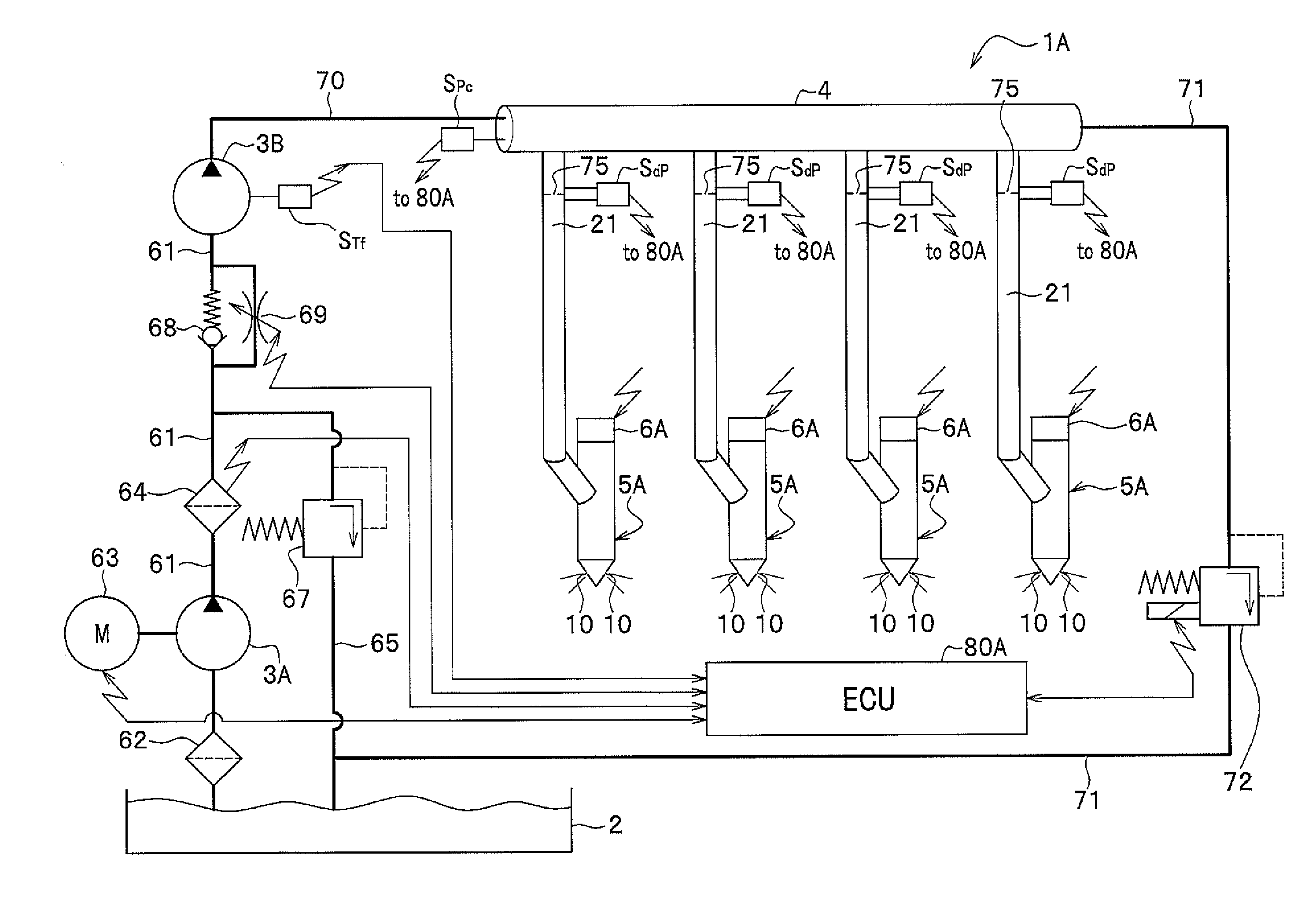
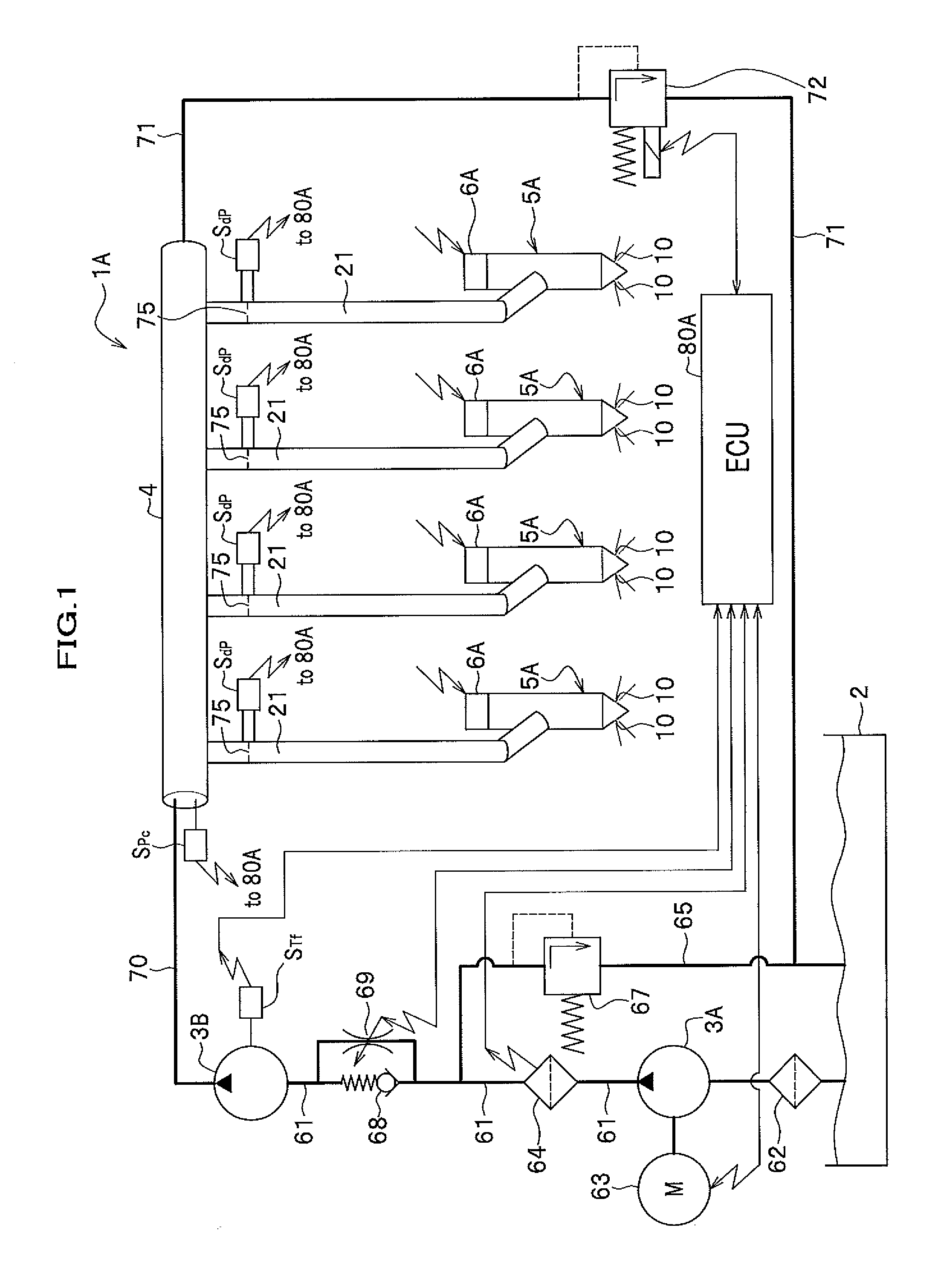
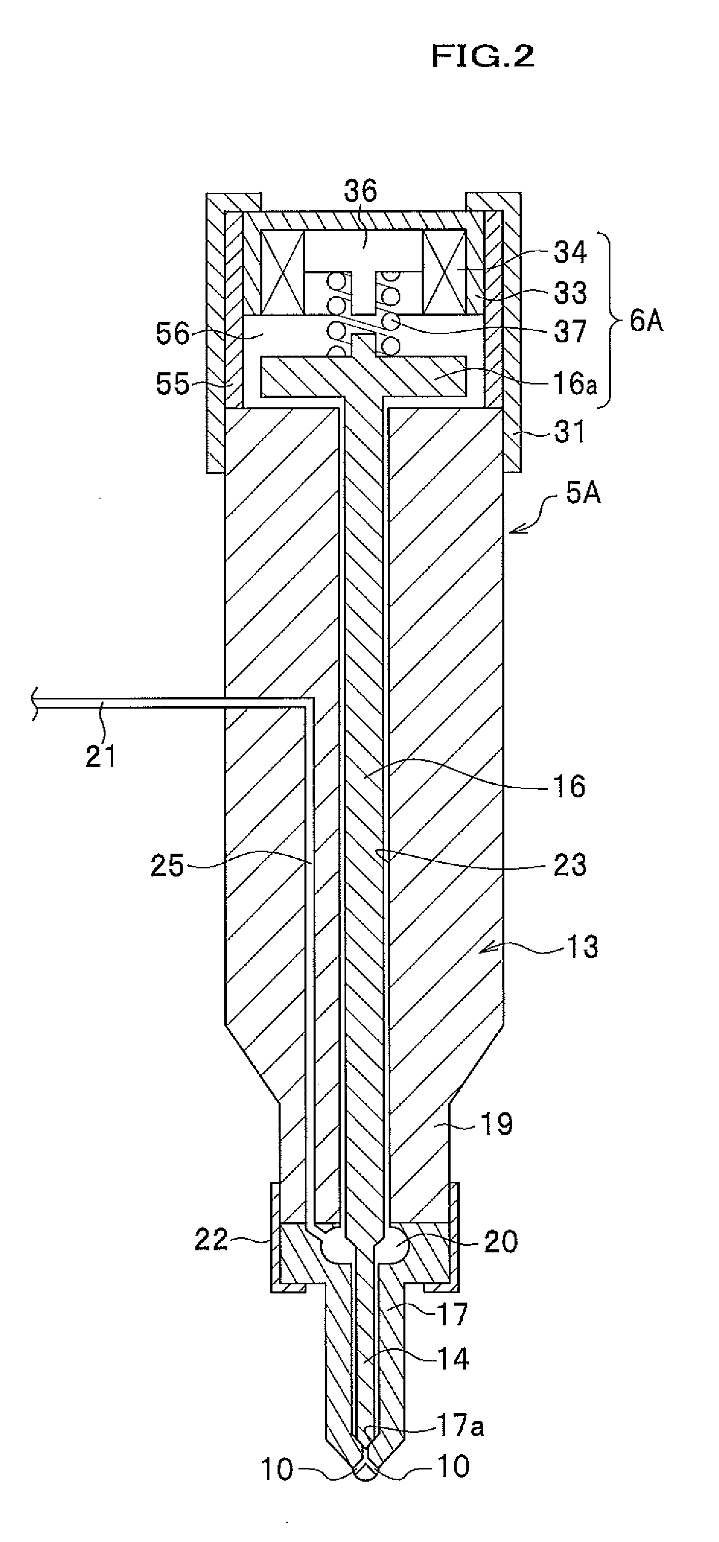
[0302]FIG. 10 is an illustration showing an entire configuration of an accumulator fuel injection device of the fourth embodiment. FIG. 11 is a conceptional configuration drawing of a back pressure fuel injection valve (injector) which is used in the accumulator fuel injection device according to the fourth embodiment.

[0303]A fuel injection device 1D of the fourth embodiment differs from the fuel injection device 1A of the first embodiment in that: (1) an injector 5B including an actuator 6B, which is a back pressure fuel, injection valve, is used; (2) in accordance with (1), a drain passage 9 is connected to the injector 5B provided in each cylinder, and the drain passages 9 are further connected to a return fuel, pipe 73, which is connected to the low pressure fuel supply passage 61 on the discharge side of the low pressure pump 3A via a flo...

fifth embodiment

[0340]Next, a fuel injection device according to a fifth embodiment of the present invention is described in detail with reference to FIG. 13.

[0341]FIG. 13 is an illustration for showing an entire configuration of the accumulator fuel injection device of the fifth embodiment.

[0342]The fuel injection device 1E differs from the fuel injection device 1D of the fourth embodiment in that: (1) a pressure sensor SPs for detecting the pressure on the downstream side of the orifice 75 is provided instead of a differential pressure sensor SdP for detecting the pressure difference between the upstream side and the downstream side of the orifice 75 which is provided in the high pressure fuel supply passage 21 for supplying fuel to the injector 5B attached to each cylinder of the engine; (2) an ECU (control unit) 80E is provided instead of the ECU 80D; (3) the definition of the orifice differential pressure ΔPOR which is used for calculating the orifice passing flow rate QOR of fuel in the ECU 8...


PUM


Abstract

A fuel injection device 1A which includes a common rail 4 for accumulating fuel delivered by a high pressure pump 3B in a pressure-accumulated state, an injector for injecting in a cylinder of the diesel engine fuel supplied through a high pressure fuel supply passage 21 branched from the common rail 4, and an ECU 80A for outputting an injection command signal for injecting the fuel from the injector 5A. The fuel injection device 1A further includes an orifice 75 in the high pressure fuel supply passage 21 on the side of the common rail 4, and a differential pressure sensor SdP for detecting the pressure difference of the pressures on the upstream and downstream sides of the orifice 75. The ECU 80A calculates an actual fuel supply amount that passes the orifice 75 based on a signal from the differential pressure sensor SdP.

Description

CROSS REFERENCE TO RELATED APPLICATIONS[0001]This application claims the foreign priority benefit under 35 U.S.C. § 119 of Japanese Patent Application No. 2008-165383 filed on Jun. 25, 2008, Japanese Patent Application No. 2008-279585 filed on Oct. 30, 2008, Japanese Patent Application No. 2008-279965 filed on Oct. 30, 2008, and Japanese Patent Application No. 2008-272915 filed on Oct. 23, 2008, the disclosures of which are incorporated herein by reference.BACKGROUND OF THE INVENTION[0002]1. Field of the Invention[0003]The present invention relates to a fuel injection device which feeds fuel accumulated in a fuel accumulation part in a pressure-accumulated state to each cylinder of an internal combustion engine from a fuel injector.[0004]2. Description of Related Art[0005]In conventional fuel injection to each cylinder, an engine controlling device (corresponding to a control unit in the present invention) calculates a fuel injection amount based on an operating condition of a vehic...

Claims


Application Information

Patent Timeline
Patent Type & Authority Applications(United States)
IPC IPC(8): F02D41/30F02M63/00
CPCF02D41/008F02D41/3809F02D41/402F02D2200/0602F02M2200/315F02D2250/04F02M63/0225F02M2200/24F02M2200/28F02D2200/0616
Inventor YUASA, HIROYUKIAKIYAMA, HIROSHITOKORO, MAMORU
Owner HONDA MOTOR CO LTD
Why Eureka
Try Eureka