Multi-mode hammering machine

a multi-mode, hammering machine technology, applied in forging/hammering/pressing machines, forging tools, forging presses, etc., can solve the problems of ram stroke and crushing of metal, not necessarily producing all the metal flow or completely compressing the metal sheet, and not being strong enough to compress and reduce the thickness of metal workpieces

Active Publication Date: 2010-01-07
JPW IND
View PDF4 Cites 5 Cited by
  • Summary
  • Abstract
  • Description
  • Claims
  • Application Information

AI Technical Summary

Problems solved by technology

The motor and rigid stroke drive system are not typically strong enough to compress and reduce the thickness of the metal workpiece.
The first stroke of the machine does not necessarily produce all the metal flow or entirely compress the sheet of metal.
The ram stroke and crushing of the metal can actually exceed the gap setting particularly after several strokes of the ram.
Yet, conventional machines do not allow stroke length and gap adjustments during the operation of the machine.
These machines are also known to produce extra impact power given the motor and stroke length of the machine.
A problem in the metal forming industry is meeting customer demands to perform a wide variety of metal forming jobs.
Yet, metal forming machines are typically quite expensive.
While one machine is being used for a specific type of job, other machines sit idle.
In addition, a single shop often needs to two or more of each machine to meet order schedules and work flow requirements, and have a back up when one machine goes down unexpectedly or is out of service for scheduled maintenance.
Combining different metal forming machines is either structurally difficult or commercially impossible.
The structures of the drive mechanisms are not readily combined, and are not readily switched from one mode of operation to another.
Integrating the power systems, drive mechanisms, frame housings and tool movements so a single machine can perform a variety of functions is a significant engineering challenge and usually commercially impossible.
As a result, metal forming shops have had to incur the expense of buying and allocating floor space for various shaping, hammering and press machines, or endure the consequences of failing to meet customer expectations.
Another problem with combining rigid reciprocating, flexible power enhancing and press machines is that their drive mechanisms must interface with both a mechanism for adjusting the ram stroke length and a mechanism for adjusting the gap between the ram and die.
A further problem with combining rigid reciprocating and flexible power enhancing metal forming machines is that the stroke length and gap should be structures so that each can be adjusted on-the-fly or during the operation of the machine.
A still further problem with combining rigid reciprocating and flexible power enhancing metal forming machines is that the forces involved are significant.
If this is not done, the components will be prone to brake or accelerated wear and tear, which will increase service costs and short the life of the machine.
A still further problem with combining rigid reciprocating and flexible power enhancing metal forming machines is the shape of the machines.

Method used


Image

  • Multi-mode hammering machine
  • Multi-mode hammering machine
  • Multi-mode hammering machine

Examples


Embodiment Construction

[0043]While this invention is susceptible of embodiment in many different forms, the drawings show and the specification describes in detail a preferred embodiment of the invention. It should be understood that the drawings and specification are to be considered an exemplification of the principles of the invention. They are not intended to limit the broad aspects of the invention to the embodiment illustrated.

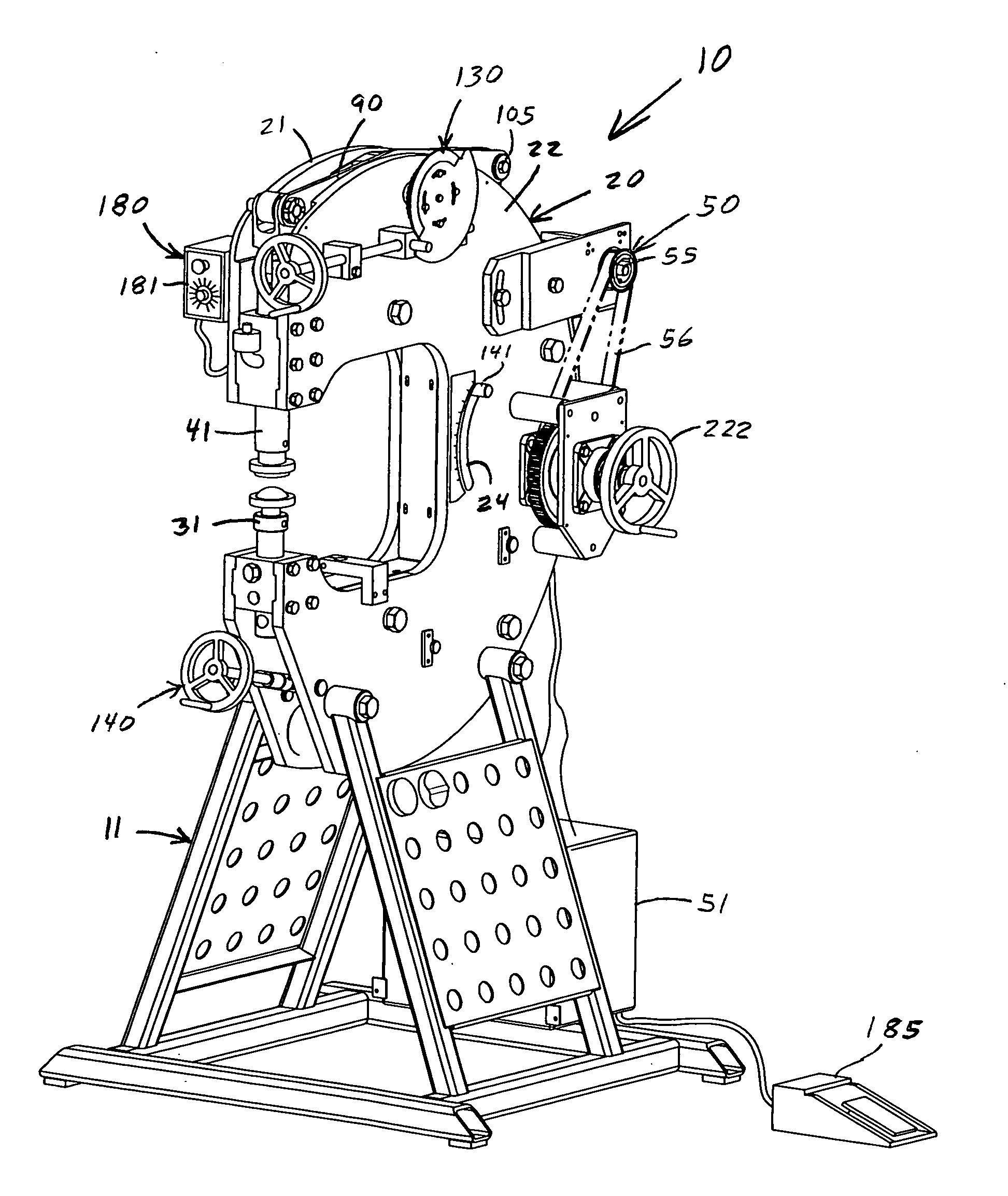
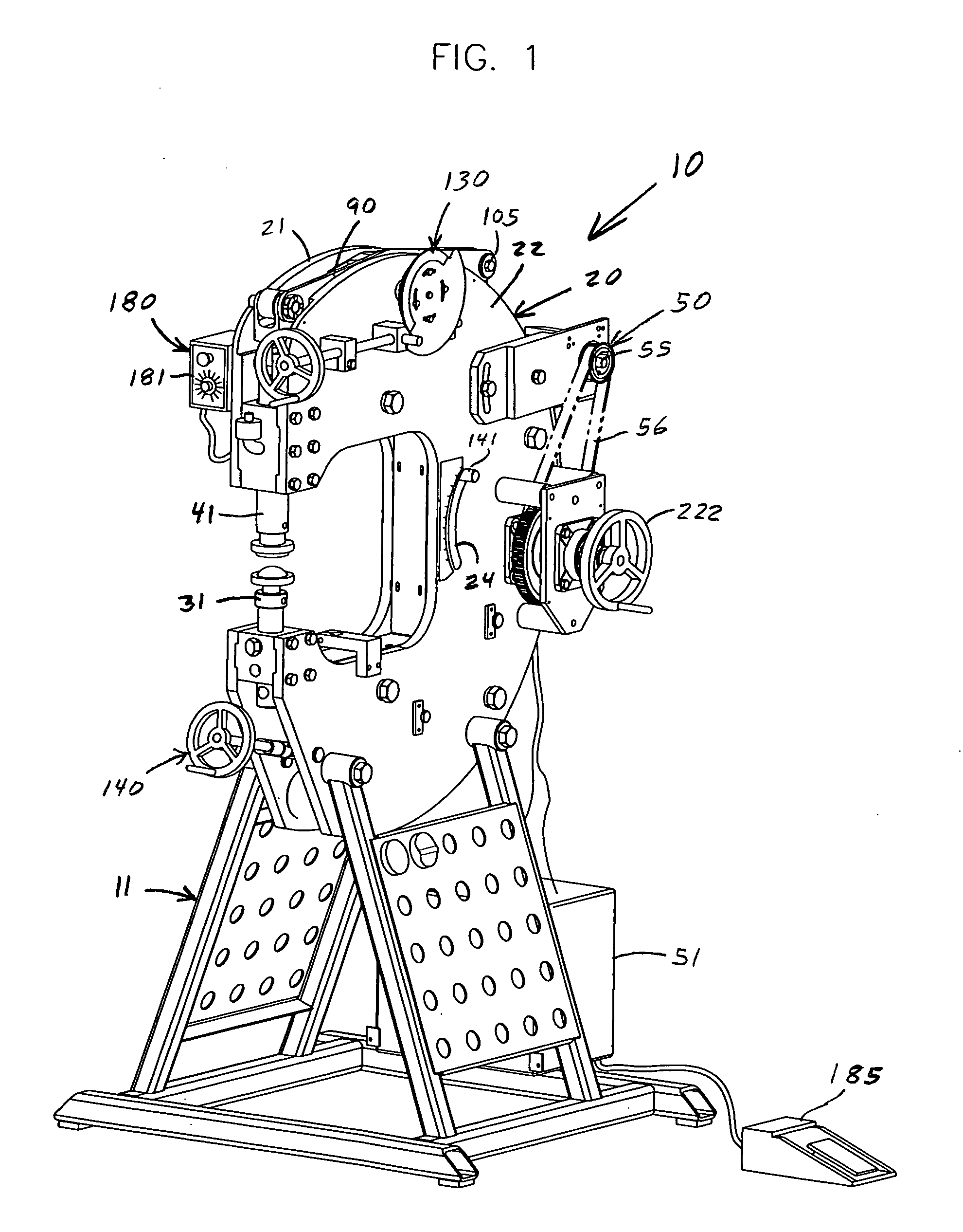
[0044]The present invention relates to a multi-mold hammering machine for shaping a workpiece 5 such as a sheet of metal. The multi-mode hammering machine is generally depicted as reference number 10 in FIG. 1. The machine 10 has a rigid meal shaping mode 190 where its ram has a rigid non-flexible stroke length. The machine 10 is readily switched from this mode to a flexible power hammer mode 200 by removing a conversion pin. In this mode, the ram has a flexible stroke length that varies with machine cycle speed. This power hammer mode utilizes a harmonic force multiplier to p...


PUM

PropertyMeasurementUnit
ram stroke length SLMaxaaaaaaaaaa
ram stroke lengthaaaaaaaaaa
weightaaaaaaaaaa

Abstract

The invention is a multi-mode hammering machine that operates in a rigid mode, a flexible power hammer mode and a machine press mode to contour, shape and form sheet metal products. In all three modes, a ram is linearly stroked toward and away from a fixed die by a common ram drive assembly that includes a lever drive assembly and a reciprocating lever. The lever drive assembly moves in a rigid non-flexing manner. The reciprocating lever includes a rigid mode and a flexible mode. A conversion pin is used to engage one and simultaneously disengage the other. The lever drive assembly includes a control link that interfaces with a stroke adjustment mechanism. The gap adjustment mechanism is located at the fulcrum of the reciprocating lever. Both stroke length and gap are adjusted independently during the operation while the ram is cycling.

Description

TECHNICAL FIELD OF THE INVENTION[0001]This invention relates to a hammering machine for shaping sheet metal that operates in a rigid-stroke mode, a flexible-stroke hammering mode, and a rigid-stroke machine press mode, and where the ram stroke length and tool gap adjustment mechanisms are independently adjustable during operation.BACKGROUND OF THE INVENTION[0002]Sheet metal shaping, hammering and pressing machines are well known. These machines typically have a fixed die and a ram that moves toward and away from the die. A metal sheet is placed on the die and the ram is lowered to shape, hammer or press the workpiece. Shaping machines have contoured male and female tools fixed to the die and ram that cause the sheet to take the shape of the tools, but do not compress or hammer the sheet metal. The tools are kept apart a distance or gap equal to the thickness of the sheet metal workpiece. The sheet metal takes on a curved or other desired shape dictated by of the ram and die tools. H...

Claims


Application Information

Patent Timeline
Patent Type & Authority Applications(United States)
IPC IPC(8): B21D7/06B21J9/18
CPCB21J7/32B21J7/02
Inventor RUSCH, CHRISTOPHER J.
Owner JPW IND
Why Eureka
Try Eureka