

Particulate matter detection device and particulate matter detection method
- Summary
- Abstract
- Description
- Claims
- Application Information
AI Technical Summary
Benefits of technology
Problems solved by technology
Method used
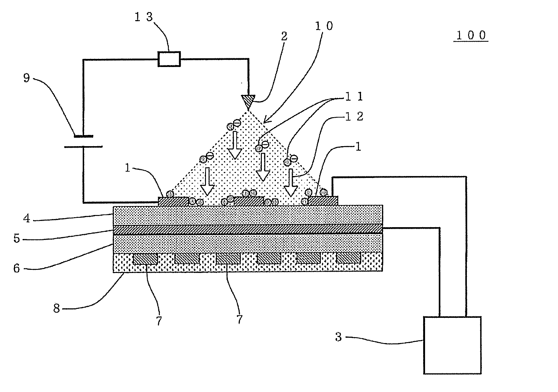
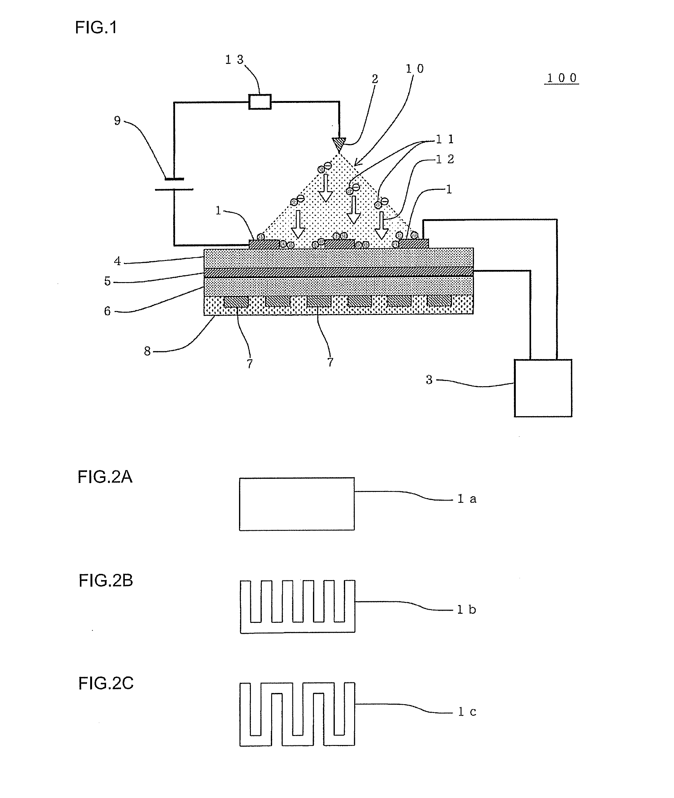
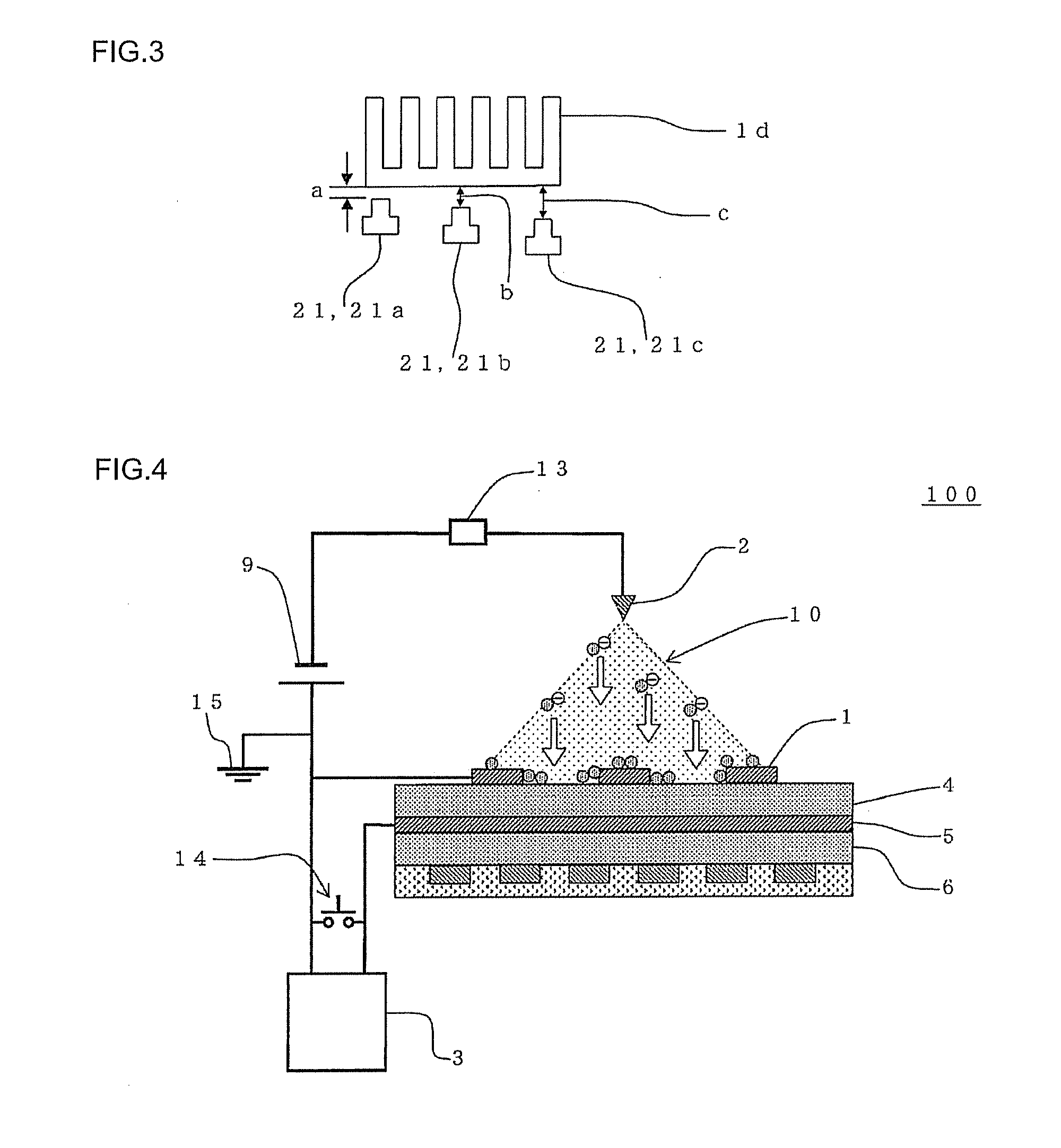
Image

Examples
example 1
(Laminate of Electrodes, Dielectrics, etc.)
[0200]An alumina pot was charged with alumina (ceramic raw material), polyvinyl butyral (binder), di(2-ethylhexyl)phthalate (plasticizer), sorbitan trioleate (dispersant), and an organic solvent (xylene:butanol=6:4 (mass ratio)). The components were mixed to prepare a forming raw material slurry for forming a green sheet. 7 parts by mass of the binder, 3.5 parts by mass of the plasticizer, 1.5 parts by mass of the dispersant, and 100 parts by mass of the organic solvent were used based on 100 parts by mass of alumina.
[0201]The resulting forming raw material slurry for green sheet was stirred under reduced pressure to remove bubbles, and the viscosity of the forming raw material slurry was adjusted to 4 Pa·s. The viscosity of the slurry was measured using a B type viscometer.
[0202]The forming raw material slurry obtained by the above method was formed into a sheet using a doctor blade method. The thickness of the green sheet was 250 μm. The ...
example 2
[0223]A particulate matter detection device similar to the particulate matter detection device 200 shown in FIG. 8 was produced, except that the back-side electrode 56, the heater 57, and the heat insulator 58 were not provided.
[0224](Laminate of Electrodes, Inter-Electrode Dielectric, etc.)
[0225]An alumina pot was charged with alumina (ceramic raw material), polyvinyl butyral (binder), di(2-ethylhexyl)phthalate (plasticizer), sorbitan trioleate (dispersant), and an organic solvent (xylene:butanol=6:4 (mass ratio)). The components were mixed to prepare a forming raw material slurry for forming a green sheet. 7 parts by mass of the binder, 3.5 parts by mass of the plasticizer, 1.5 parts by mass of the dispersant, and 100 parts by mass of the organic solvent were used based on 100 parts by mass of alumina.
[0226]The resulting forming raw material slurry was stirred under reduced pressure to remove bubbles, and the viscosity of the forming raw material slurry was adjusted to 4 Pa·s. The...
PUM
| Property | Measurement | Unit |
|---|---|---|
| Electric potential / voltage | aaaaa | aaaaa |
| Electrostatic force | aaaaa | aaaaa |
| Electric impedance | aaaaa | aaaaa |
Abstract
Description
Claims
Application Information