
Particulate matter detection device and particulate matter detection method

a detection device and technology for particulate matter, applied in the direction of machines/engines, electrostatic separation, electrical supply techniques, etc., can solve the problems of large error, increased cost, and measurement of particulate matter, and achieve the effect of reducing measurement errors, simple detection, and simple detection

Inactive Publication Date: 2011-01-04
NGK INSULATORS LTD
View PDF29 Cites 7 Cited by
  • Summary
  • Abstract
  • Description
  • Claims
  • Application Information

AI Technical Summary

Benefits of technology

The device effectively detects particulate matter with reduced measurement errors and costs by leveraging impedance changes, allowing for precise quantification of particulate matter in exhaust gases.

Problems solved by technology

According to such a method where particulate matter is charged and ion current is detected, since the ion current due to the particulate matter is weak, a large-scale detection circuit is required to detect such a weak ion current so that costs increase.
Moreover, since the particulate matter cannot be effectively charged when the exhaust gas flows at a high flow rate, the amount of particulate matter measured may be smaller than the amount of particulate matter actually contained in the exhaust gas (i.e., a large error may occur).

Method used


Image

  • Particulate matter detection device and particulate matter detection method
  • Particulate matter detection device and particulate matter detection method
  • Particulate matter detection device and particulate matter detection method

Examples


example 1

Laminate of Electrodes, Dielectrics, Etc.

[0192]An alumina pot was charged with alumina (ceramic raw material), polyvinyl butyral (binder), di(2-ethylhexyl)phthalate (plasticizer), sorbitan trioleate (dispersant), and an organic solvent (xylene:butanol=6:4 (mass ratio)). The components were mixed to prepare a forming raw material slurry for forming a green sheet. 7 parts by mass of the binder, 3.5 parts by mass of the plasticizer, 1.5 parts by mass of the dispersant, and 100 parts by mass of the organic solvent were used based on 100 parts by mass of alumina.

[0193]The resulting forming raw material slurry for green sheet was stirred under reduced pressure to remove bubbles, and the viscosity of the forming raw material slurry was adjusted to 4 Pa·s. The viscosity of the slurry was measured using a B type viscometer.

[0194]The forming raw material slurry obtained by the above method was formed into a sheet using a doctor blade method. The thickness of the green sheet was 250 μm. The gr...

example 2

[0216]A particulate matter detection device similar to the particulate matter detection device 200 shown in FIG. 8 was produced, except that the back-side electrode 56, the heater 57, and the heat insulator 58 were not provided.

[0217](Laminate of Electrodes, Inter-Electrode Dielectric, etc.)

[0218]An alumina pot was charged with alumina (ceramic raw material), polyvinyl butyral (binder), di(2-ethylhexyl)phthalate (plasticizer), sorbitan trioleate (dispersant), and an organic solvent (xylene:butanol=6:4 (mass ratio)). The components were mixed to prepare a forming raw material slurry for forming a green sheet. 7 parts by mass of the binder, 3.5 parts by mass of the plasticizer, 1.5 parts by mass of the dispersant, and 100 parts by mass of the organic solvent were used based on 100 parts by mass of alumina.

[0219]The resulting forming raw material slurry was stirred under reduced pressure to remove bubbles, and the viscosity of the forming raw material slurry was adjusted to 4 Pa·s. The...


PUM

PropertyMeasurementUnit
distanceaaaaaaaaaa
distanceaaaaaaaaaa
distanceaaaaaaaaaa

Abstract

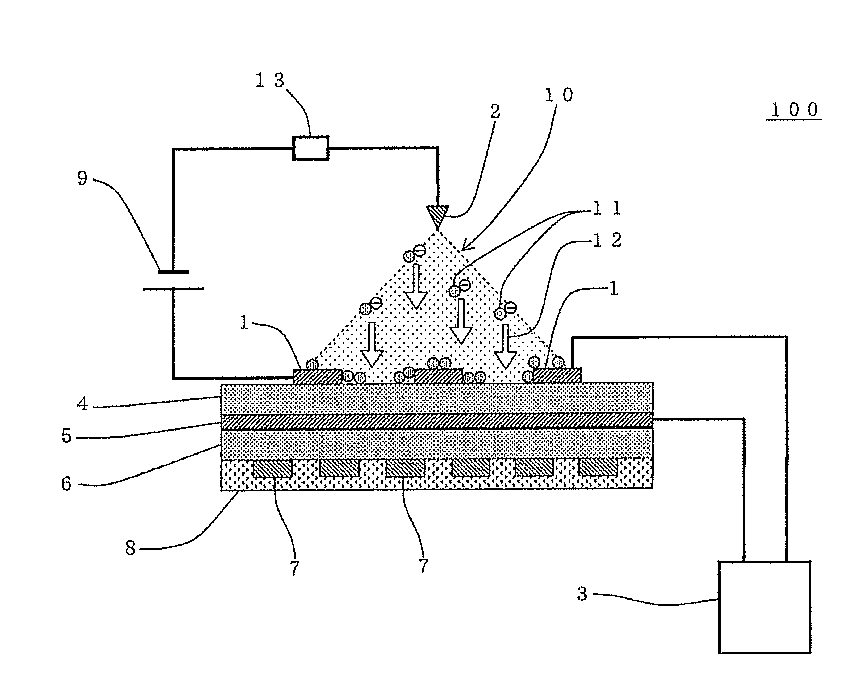
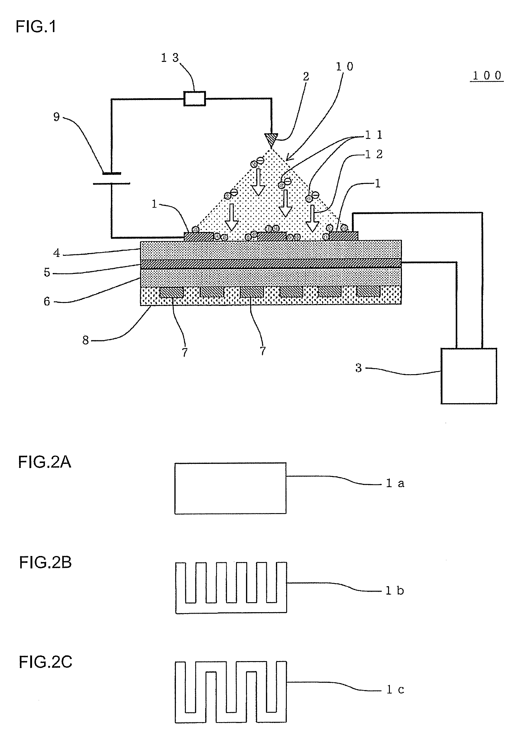
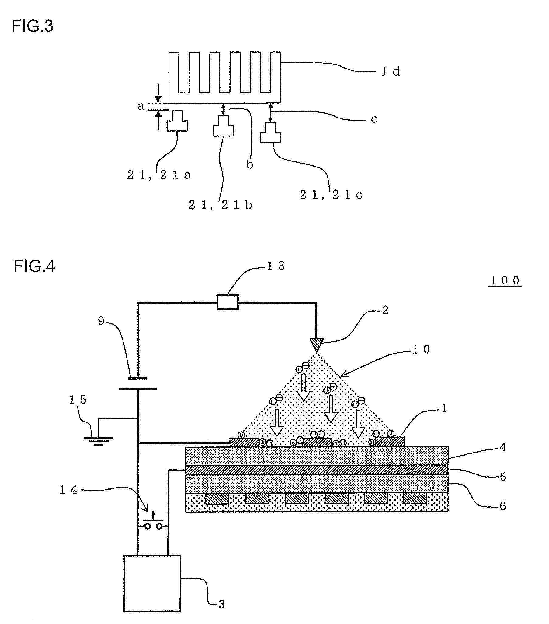
A particulate matter detection device includes a collection electrode that collects the particulate matter, a discharge electrode that allows a corona discharge to occur when a voltage is applied between the collection electrode and the discharge electrode, a measurement electrode, the impedance between the collection electrode and the measurement electrode changing when the collection electrode has collected the particulate matter, and a measurement section that detects a change in the impedance between the collection electrode and the measurement electrode, the particulate matter detection device detecting the particulate matter by charging the particulate matter contained in the gas by utilizing the corona discharge, collecting the charged particulate matter by the collection electrode by utilizing an electrostatic force, and detecting a change in the impedance between the collection electrode that has collected the particulate matter and the measurement electrode using the measurement section.

Description

FIELD OF THE INVENTION[0001]The present invention relates to a particulate matter detection device and a particulate matter detection method. More particularly, the present invention relates to a particulate matter detection device and a particulate matter detection method that can simply detect particulate matter with a small measurement error.BACKGROUND OF THE INVENTION[0002]A flue gas or a diesel engine exhaust gas contains particulate matter (PM) (e.g., soot) that causes air pollution. A filter (diesel particulate filter (DPF)) formed of a ceramic or the like has been widely used to remove them. A DPF formed of a ceramic can be used for a long period of time, but may suffer defects (e.g., cracks) due to thermal deterioration or the like so that a small amount of particulate matter may leak from the DPF. It is very important to immediately detect such defects and abnormalities of apparatuses from the viewpoint of preventing air pollution. The amount of particulate matter discharg...

Claims


Application Information

Patent Timeline
Patent Type & Authority Patents(United States)
IPC IPC(8): B03C3/68
CPCF01N2560/05G01N15/0656Y10S55/10F01N3/02G01N27/68G01N15/06
Inventor SAKUMA, TAKESHIFUJIOKA, YASUMASAKONDO, ATSUO
Owner NGK INSULATORS LTD
Learn More